


11
OPERATION
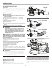
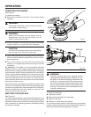
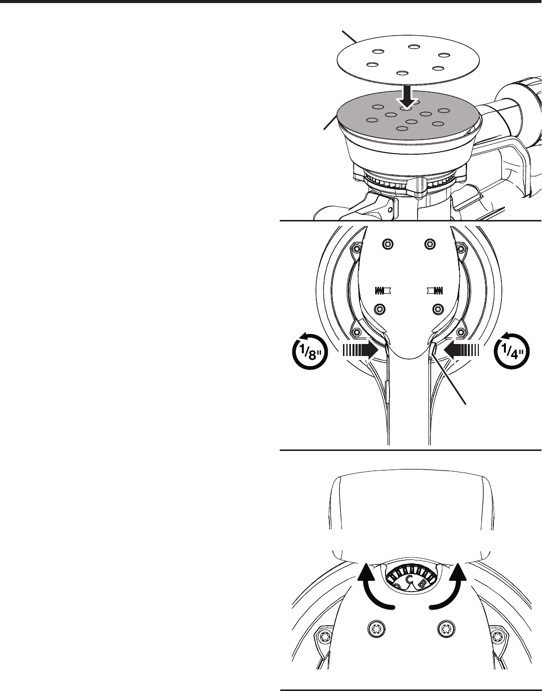
ATTACHING HOOK AND LOOP SANDING
DISC
See Figure 3.
To attach hook and loop sanding disc:
Unplug the sander.
Align the holes in the sanding disc with the holes in the
hook and loop backing pad.
Press the sanding disc against the backing pad as firmly
as possible.
NOTE: To provide for the best adhesion, we recom-
mend that you clean the backing pad and the sanding
disc backing occasionally by brushing them lightly with
a small brush.
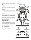
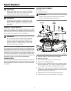
SELECTING THE ORBIT DIAMETER
See Figure 4.
The dual random orbit selector allows you to choose
between two orbits: the 1/8 in. orbit setting produces a
finer surface finish, while the 1/4 in. orbit setting increases
the removal rate.
With the sander held in normal operating position, the dual
random orbit selector should be positioned to the left of the
switch trigger for a 1/4 in. orbit diameter. The dual random
orbit selector should be positioned to the right of the switch
trigger for a 1/8 in. orbit diameter.
VARIABLE SPEED DIAL
See Figure 5.
The variable speed dial allows the sander to operate at
speeds that can be adjusted by rotating the dial from A to F.
The dial is conveniently located on the motor hous ing, allow-
ing operator control of disc speed. To in crease sanding disc
speed, turn the vari able speed dial to a higher setting. Turn
dial to a lower setting to decrease sanding disc speed.
Recommended speed settings are as follows:
Speed Surface/Application
A - B plastic, plexiglass
C - D metal finishing, old paint removal
E - F wood/coarse and fine sanding
HOOK
AND LOOP
BACKING PAD
SANDING DISC
Fig. 4
DUAL RANDOM
ORBIT SELECTOR
Fig. 3
Fig. 5
TO INCREASE SPEED TO DECREASE SPEED