15
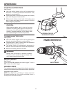
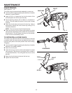
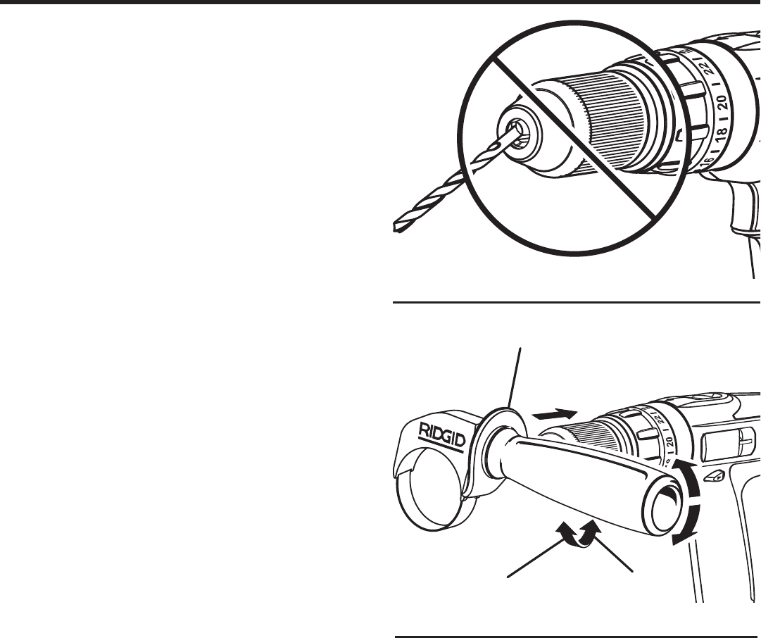
Fig. 12
OPERATION
Fig. 11
WRONG
TO
TIGHTEN
AUXILIARY HANDLE
ASSEMBLY
TO
LOOSEN
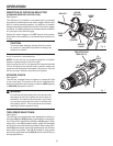
USING THE AUXILIARY HANDLE ASSEMBLY
See Figure 12.
An auxiliary handle assembly is packed with the drill for
ease of operation and to help prevent loss of control. The
handle can be rotated 360°, and it can also be mounted on
the opposite side for left hand use.
To adjust the auxiliary handle assembly,
Loosen the handle assembly by turning the handle coun-
terclockwise.
Rotate the handle assembly to the desired operating
position.
Securely tighten by turning the handle assembly clock-
wise.
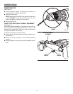
REMOVING BITS
See Figure 10.
Lock the switch trigger by placing the direction of
rotation selector in the center position.
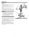
Open the chuck jaws.
NOTE: Rotate the chuck body in the direction of the arrow
marked UNLOCK to open the chuck jaws. Do not use a
wrench to tighten or loosen the chuck jaws.
Remove the drill bit.


