


12
22
20
18
16
14
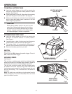
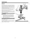
OPERATION
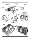
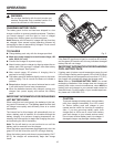
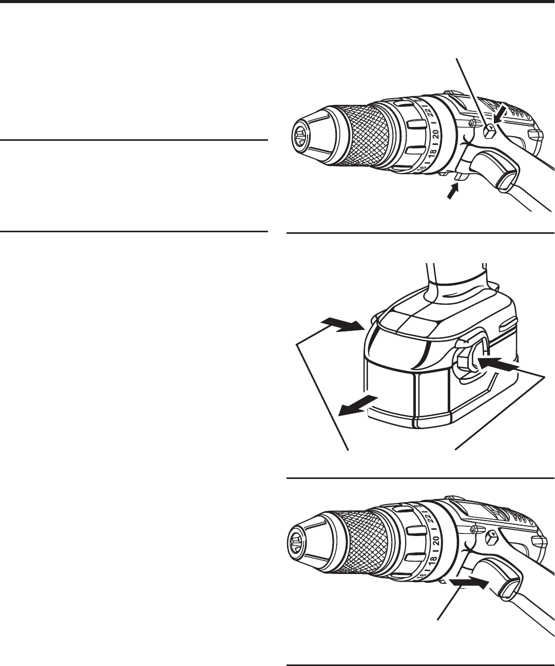
TO INSTALL BATTERY PACK
n Lock the switch trigger on the drill by placing the
direction of rotation (forward-reverse) selector in center
position. See Figure 4.
n Place battery pack in the drill. Align raised rib on battery
pack with the groove inside the drill. See Figure 5.
n Make sure the latches on each side of your battery pack
snap in place and battery pack is secured in the drill
before beginning operation.
CAUTION:
When placing battery pack in the tool, be sure
raised rib on battery pack aligns with the slide on
the bottom of the drill and latches snap into place
properly. Improper assembly of the battery pack
can cause damage to internal components.
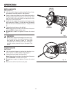
TO REMOVE BATTERY PACK
n Lock the switch trigger on the drill by placing the
direction of rotation selector in center position.
See Figure 4.
n Locate latches on side of battery pack and depress to
release battery pack from the drill. See Figure 5.
n The battery pack will automatically disconnect in
direction to be removed when buttons are depressed.
n Remove the battery pack from your drill.
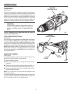
SWITCH
See Figure 6.
To turn your drill ON, depress the switch trigger. To turn it
OFF, release the switch trigger.
VARIABLE SPEED
See Figure 6.
This tool has a variable speed switch that delivers higher
speed and torque with increased trigger pressure. Speed is
controlled by the amount of switch trigger depression.
This drill has an electric brake. When the trigger switch
is released, the chuck stops turning. When the brake is
functioning properly, sparks will be visible through the vent
slots on the housing. This is normal and is the action of
the brake.
Note: You might hear a whistling or ringing noise from the
switch during use. Do not be concerned, this is a normal
part of the switch function.
Fig. 4
Fig. 5
DEPRESS LATCHES TO
RELEASE BATTERY PACK
Fig. 6
VARIABLE SPEED
SWITCH TRIGGER
SELECTOR WITH CENTER
LOCK POSITION
FORWARD
REVERSE