


16
OPERATION
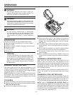
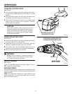
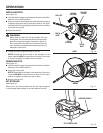
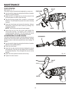
USING THE AUXILIARY HANDLE ASSEMBLY
See Figure 13
An auxiliary handle assembly is packed with the drill for
ease of operation and to help prevent loss of control. The
handle can be rotated 360°, and it can also be mounted on
the opposite side for left hand use.
To adjust the auxiliary handle assembly,
Loosen the handle assembly by turning the handle
counterclockwise.
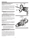
Rotate the handle assembly to the desired operating
position.
Securely tighten by turning the handle assembly
clockwise.
Be sure the handle assembly is securely tightened against
the clamp. This secures the handle assembly.
NOTE: For convenience and ease of starting threads, the
hex nut has been trapped inside the molded slot in the
handle assembly.
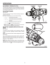
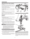
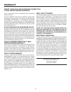
DRILLING
See Figure 14.
Check the direction of rotation selector for the correct
setting (forward or reverse).�
Secure the material to be drilled in a vise or with clamps
to keep it from turning as the drill bit rotates.�
Hold the drill firmly and place the bit at the point to be
drilled.�
Depress the switch trigger to start the drill.
Move the drill bit into the workpiece, applying only enough
pressure to keep the bit cutting. Do not force the drill or
apply side pressure to elongate a hole. Let the tool do
the work.
WARNING:
Be prepared for binding at bit breakthrough. When
these situations occur, drill has a tendency to grab
and kick opposite to the direction of rotation and
could cause loss of control when breaking through
material. If not prepared, this loss of control can
result in possible serious injury.
When drilling hard, smooth surfaces, use a center punch
to mark the desired hole location. This will prevent the
drill bit from slipping off-center as the hole is started.
When drilling metals, use a light oil on the drill bit to keep
it from overheating. The oil will prolong the life of the bit
and increase the drilling action.
If the bit jams in the workpiece or if the drill stalls, stop
the tool immediately. Remove the bit from the workpiece
and determine the reason for jamming.
TO
LOOSEN
Fig. 13
Fig. 14
360°
ROTATION
TO
TIGHTEN
AUXILIARY
HANDLE
NOTE: This drill has an electric brake. When the switch
trigger is released, the chuck stops turning. When the brake
is functioning properly, sparks will be visible through the
vent slots on the housing. This is normal and is the action
of the brake.