


13
OPERATION
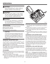
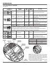
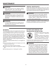
DIRECTION OF ROTATION SELECTOR
See Figure 6.
The direction of bit rotation is reversible and is controlled by
a selector located above the switch trigger. With the impact
driver held in normal operating position, the direction of rota-
tion selector should be positioned to the left of the switch
trigger for driving. The driving direction is reversed when the
selector is to the right of the switch trigger.
Setting the switch trigger in the OFF (center lock) position
helps reduce the possibility of accidental starting when not
in use.
CAUTION: To prevent gear damage, always allow the
coupler to come to a complete stop before changing
the direction of rotation.
To stop the impact driver, release the switch trigger and allow
the coupler to come to a complete stop.
NOTE: The impact driver will not run unless the direction of
rotation selector is pushed fully to the left or right.
Avoid running the driver at low speeds for extended
periods of time. Running at low speeds under constant
usage may cause the driver to become overheated. If this
occurs, cool the driver by running it without a load and at
full speed.
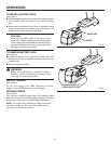
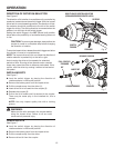
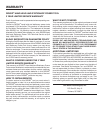
INSTALLING BITS
See Figure 7.
Lock the switch trigger by placing the direction of
rotation selector in the center position.
Remove the battery pack from the impact driver.
Pull the coupler away from the driver (1).
Insert driver bit to be used into the coupler (2).
Release the coupler (3).
Pull on the bit to make sure it is secured in the coupler.
There may be some play in the installed bit; this is
normal.
NOTE: Use only impact quality bits with a locking
groove.
WARNING:
Make sure the bit is secured in the coupler before
using the impact driver. Failure to do so could
cause serious personal injury.
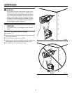
REMOVING BITS
See Figure 7.
Lock the switch trigger by placing the direction of
rotation selector in the center position.
Remove the battery pack from the impact driver.
Pull the coupler away from the driver.
Remove driver bit from the coupler.
Fig. 6
DIRECTION OF ROTATION SELECTOR
(FORWARD/REVERSE/CENTER LOCK)
SWITCH
TRIGGER
FORWARD
REVERSE
BIT
Fig. 7
1
2
3
PULL COUPLER
FORWARD
INSERT BIT
RELEASE COUPLER
COUPLER
LOCKING GROOVE