


INTRODUCTION
Thank you for your purchase of the CL151 GLC Gate Compressor Limiter. This unit pro-
vides smooth, soft-knee compression and limiting with a gate. Gain reduction is indicated
via a front panel 5-segment LED bargraph. Plus, the unit has a mic preamp input with 12
volts phantom power available.
WARRANTY INFO
Please visit our website,
www.rolls.com
, for the Rolls 1 Year Warranty information and
registration.
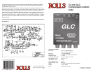
FRONT PANEL
INPUT: Adjusts the amount of input signal to the CL151, from no signal to +20 dB.
GATE REL: This control adjusts the amount of time taken for the gate circuitry to "close" or
mute the output, after the signal level has dropped below the gate Threshold level.
THRESH: Sets the point at which the input signal must surpass to "open" the gate circuitry
or allow signal to pass to the output.
GATE LED: When lit, indicates that the gate is "closed" or the output is muted.
COMP RATIO: This control sets the signal to compression ratio. This ratio relates to the
amount of increase of input compared to output signal. Thus, at a 1:1 ratio, a 1 dB in-
crease of input signal will result in a 1 dB increase of output signal. At 2:1, a 2 dB increase
of input signal will result in only 1 dB increase of output signal. At 8:1, an 8 dB increase of
input signal will result in a 1dB increase of output signal.
THRESH: Sets the point that the input signal must reach for compression to begin.
GAIN REDUCTION LEDs: This LED ladder indicates the amount of signal compression,
or gain reduction.
OUTPUT: Adjusts the amount of overall output signal from the CL151.
PWR: Indicates that the CL151 is connected to the power source, and th
e
unit is on.
REAR PANEL
MIC IN: Balanced XLR jack, for connection to any standard dynamic or condenser micro-
phone.
LINE IN: Balanced 1/4" TRS jack for connection to balanced or unbalanced line level
signals.
SIDE CHAIN: 1/4" TRS jack for connection via TRS insert cable to a device such as an
equalizer or other device, for direct access to the CL151 detector circuitry.
LINE OUT: Balanced 1/4" TRS jack for connection to a mixer's line input or to an amplifier.
DC IN: For connection to the Rolls PS27 12 VDC, 150 mA power supply; outside of the
barrel is positive.
SIDE PANEL
PHANTOM POWER: Jumper header for connecting 12 VDC phantom power to the XLR
Mic Input. Phantom power is engaged by carefully removing the jumper, and reconnecting
it to the pins toward the CL151 controls.
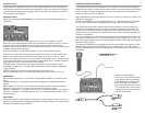
CONNECTION AND OPERATION
The example below shows the connection of a microphone. If the microphone requires
phantom power, make sure the Phantom Power jumper is connecting the two pins closest
to the front panel. Connect the output of the CL151 via a balanced or unbalanced 1/4"
plug to the input of a mixer or amplifier.
Begin adjustments by setting the INPUT and OUTPUT levels at O (about 10 O'clock). This
setting is for "unity gain".
Set the gate THRESH for "off", the COMP RATIO for 1:1, and the compressor THRESH
for +10. These initial settings essentially bypass the gate and compressor circuits.
The compressor RATIO and THRESH controls work together to control the amount of
compression, and the point at which compression begins respectively. Decreasing the
THRESH control lowers the amount of signal required to begin compression - so it com-
presses sooner. This works with the RATIO control which, when increased, increases the
amount of compression.
The gate THRESH control, after being turned slightly counterclockwise from the "off" posi-
tion, goes to its maximum level. This means it requires a higher signal level to "open" the
gate. As the gate THRESH control is turned counterclockwise, a lower and lower signal is
required to open the gate.
The gate REL (release time) control sets the amount of time taken for the gate to "close"
after the signal drops below the THRESH level. For example, the CL151 will continue
passing a sustaining note until the level drops below the THRESH level, and the REL time
has passed.
Connection Example
Connection Example
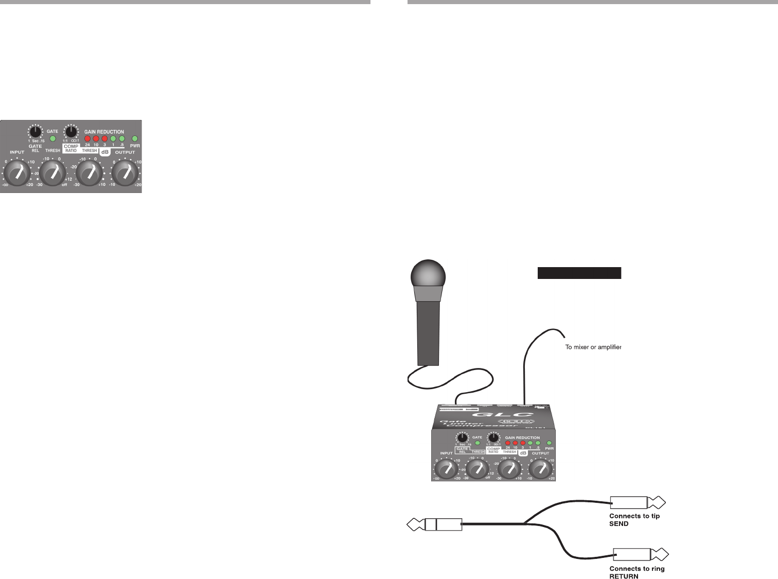
USING THE SIDE CHAIN
To access the compressor detector
circuit directly, Rolls has included
a Side Chain jack. The Side Chain
works somewhat like an effects
loop, with a send and return point. A
1/4" Tip-Ring-Sleeve "Insert Cable"
is required to utilize the Side Chain.
See the picture below.
(Explanation continues on the next page)