


15
FEED
DIRECTION
Inch
1
0
1
2
3
Inch
1
0
1
2
3
Inch
1
0
1
2
3
Inch
1
0
1
2
3
FEED
DIRECTION
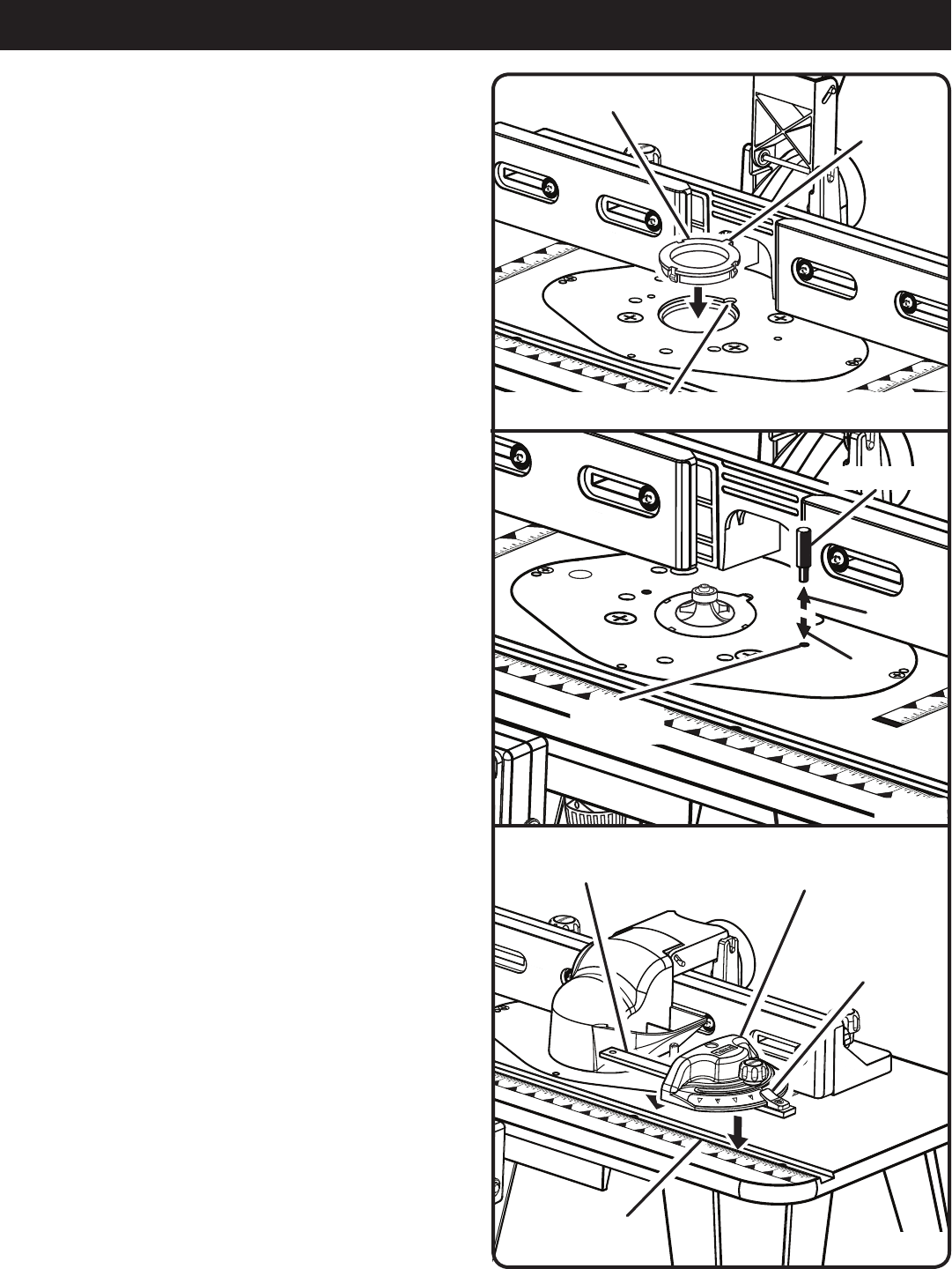
Fig. 16
STARTING
PIN HOLES
STARTING PIN
INSTALL
REMOVE
Fig. 15
ASSEMBLY
Fig. 14
Inch
1
0
1
2
3
Inch
1
0
1
2
3
FEED
DIRECTION
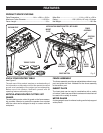
THROAT PLATE
NOTCH
TAB
MITER GAUGE
MITER
GAUGE BAR
POINTER
SLOT
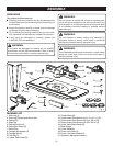
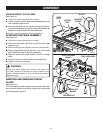
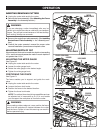
The proper size throat plate depends on the size and shape
of the cutter. When inserted, the throat plate opening should
be within approximately 1/4 in. of the outermost edge of
the cutter.
Unplug the router table and/or the router.
Select the throat plate you wish to use.
Press throat plate into insert plate slot until it snaps into
place.
To remove, push throat plate out from the bottom of the
insert plate.
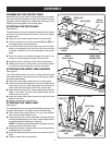
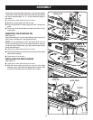
INSERTING THE STARTING PIN
See Figure 15.
Place the starting pin on the router table and use it as a pivot
point when cutting small, odd-shaped pieces.
NOTE: It is not necessary to use the fence when you are
using the starting pin, but the bit guard should be used to
cover the cutter. Additionally, only use piloted cutters when
using the starting pin.
Unplug the router table and/or the router.
Place the starting pin into the hole to the right of the router
table throat opening.
Push the pin in to secure.
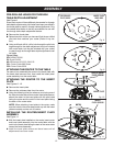
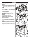
INSTALLING THE MITER GAUGE
See Figure 16.
Unplug the router table and/or the router.
With the router table right side up, and the front edge
closest to you, place the miter gauge bar in the slot near
the front of the table with the pointer on the right.