


10
Inch
1
0
1
2
3
Inch
1
0
1
2
3
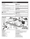
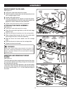
FEED
DIRECTION
3
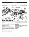
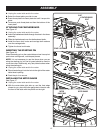
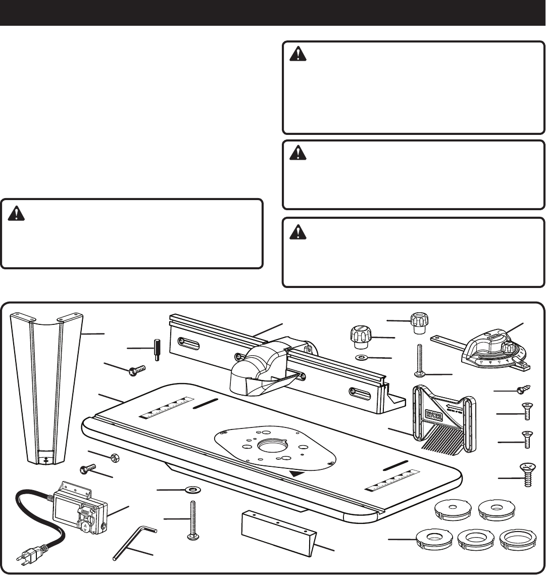
ASSEMBLY
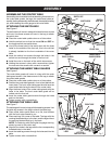
PACKING LIST
1. Table Leg (4)
2. Starting Pin
3. Table Leg Phillips Head Screw (16)
4. Table Top
5. Switch Box Nut (3)
6. Switch Box Screw (3)
7. Switch Box
8. Carriage Bolt Washer (2)
9. Carriage Bolt (2)
10. Hex Key (1)
11. Under Table Guard (2)
12. Throat Plates (5)
13. Router Insert Plate Screws (
5/16-18 x 3/4 in.) (3)
14. Router Insert Plate Screws (10-24 x 5/8 in.) (3)
15. Router Insert Plate Screws (10-32 x 5/8 in.) (3)
16. Under Table Guard Screw (6)
17. Miter Gauge
18. Fence Assembly
19. Fence Lock Knobs (2)
20. Featherboard
21. Featherboard Bolts (2)
22. Fence Lock Knob Washer (2)
23. Featherboard Lock Knobs (2)
24. Operator’s Manual (not shown)
1
5
6
7
8
9
10
11
19
20
15
16
17
Fig. 4
3
12
2
4
14
13
18
UNPACKING
This product requires assembly.
Carefully remove the product and any accessories from
the box. Make sure that all items listed in the packing list
are included.
Inspect the product carefully to make sure no breakage
or damage occurred during shipping.
Do not discard the packing material until you have care-
fully inspected and satisfactorily operated the product.
If any parts are damaged or missing, please call
1-800-525-2579 for assistance.
WARNING:
Do not attempt to modify this product or create acces-
sories not recommended for use with this product. Any
such alteration or modification is misuse and could result
in a hazardous condition leading to possible serious
personal injury.
WARNING:
Do not connect to power supply until assembly is
complete. Failure to comply could result in accidental
starting and possible serious personal injury.
WARNING:
If any parts are damaged or missing do not operate
this product until the parts are replaced. Failure to heed
this warning could result in serious personal injury.
WARNING:
The undertable guards must be securely in place before
using the router table. Failure to do so could result in
serious personal injury.
22
21
23