13
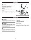
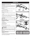
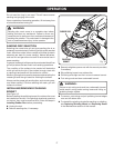
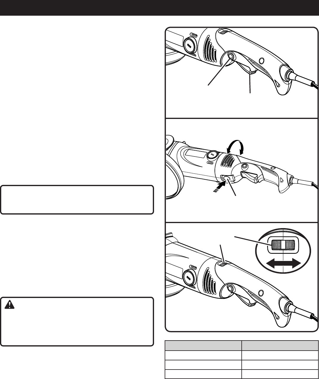
Fig. 3
lock-off/
lock-on
BuTTon
SWiTcH
TriGGer
OPERATION
LOCK-OFF/LOCK-ON BUTTON
See Figure 3.
The lock-off/lock-on button prevents accidental starting of the
grinder, and also allows the grinder to be locked-on, which
is convenient for continuous grinding/sanding/polishing for
extended periods of time.
To lock-on:
Push in and hold the lock-off/lock-on button, located on
the side of the handle.
Depress the switch trigger.
Push in further on the lock-off/lock-on button.
Release the switch trigger.
Release the lock-on button and the tool will continue
running.
To release the lock, depress and release the switch
trigger.
If the lock-on feature is engaged during use and the
tool becomes disconnected from the power supply,
disengage the lock-on feature immediately.
CAUTION:
Never cover air vents. They must always be open for
proper motor cooling.
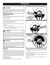
90˚ ROTATING HANDLE
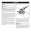
See Figure 4.
The handle on the tool can rotate 90˚ to the left or right for
ease of operation.
To adjust the handle:
Unplug the tool.
Press and hold handle lock button.
Rotate the handle to the desired position and release the
handle lock button.
WARNING:
Make sure the handle lock button on the handle clicks
and locks into place when changing handle positions.
Failure to heed this warning could result in serious per-
sonal injury.
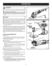
VARIABLE SPEED DIAL
See Figure 5.
The variable speed dial allows you to optimize the speed of
the tool based on the desired application. Refer to the chart
at right for proper speed selection.
Fig. 4
puSH
HAndle lock BuTTon
To roTATe HAndle
Fig. 5
vAriABle
Speed diAl
3
APPLICATION SPEED SETTING
Polishing 1-2
Sanding 3-5
Grinding 6


