


Page 9
MAINTENANCE
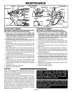
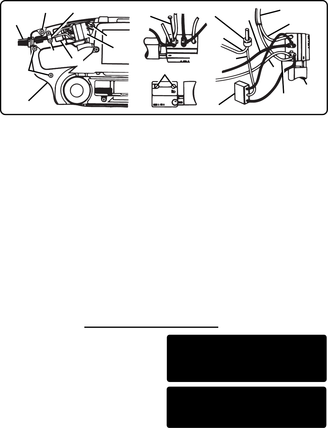
CORD REPLACEMENT
DISCONNECT THE SANDER FROM POWER SUPPLY
WHILE REPLACING PARTS OR MAKING ADJUSTMENTS.
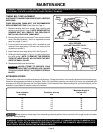
1. Remove handle cover and screws. NOTE THE
LOCATIONS OF ALL WIRING IN THE HANDLE AND
HOW EACH CONNECTION IS MADE TO THE CORD.
Connections and wiring position must be identical when
installing the new cord.
See
Figure 12.
2. Remove the cord clamp screws and cord clamp.
3. Lift the switch away from the handle. Release power cord
leads from the switch by loosening the two screws in the
switch body.
4. Remove the bend relief from the old cord and place it on
the new one.
5. Make new power cord lead connections to switch by
positioning leads in place and tightening the two screws on
the switch body. Pull on leads to check lead connections
with lead receptacles.
6. Position the switch in place, and arrange all wiring in the
handle so that it will not be pinched or contact screws when
the handle cover and screws are replaced.
See Figure 12.
7. Arrange suppressor, connectors, and suppressor leads in
the handle so that they will not be pinched or contact
screws when the handle cover and screws are replaced.
See Figure 12.
8. Replace cord clamp, cord clamp screws, handle cover,
and handle cover screws.
9. Tighten all screws securely.
Fig. 12
SWITCH REPLACEMENT
DISCONNECT THE SANDER FROM POWER SUPPLY WHILE
REPLACING PARTS OR MAKING ADJUSTMENTS.
1. Remove the handle cover and screws. NOTE THE
LOCATIONS OF ALL WIRING IN THE HANDLE AND
HOW EACH CONNECTION IS MADE TO THE SWITCH.
Connections and wiring position must be identical when
installing the new switch.
See Figure 12.
2. Lift the switch away from the handle. Release power cord
leads from the switch by loosening the two screws in the
switch body.
3. Release motor leads from switch by inserting a small
diameter pin or nail into remaining switch lead receptacles.
See Figure 12.
4. Make lead connections to the new switch by positioning
power cord leads in place and tightening the two screws
on switch body. Push motor leads as far as possible into
the switch lead receptacles. Pull on leads to check lead
connections with lead receptacles.
5. Position the switch in place, and arrange the wiring in the
handle so that it will not be pinched or contact screws
when the handle cover and screws are replaced.
See
Figure 12.
6. Arrange suppressor, connectors, and suppressor leads
in the handle so that they will not be pinched or contact
screws when the handle cover and screws are replaced.
See Figure 12.
7. Replace handle cover and screws.
8. Tighten all screws securely.
GENERAL
Avoid using solvents when cleaning plastic parts. Most
plastics are susceptible to various types of commercial
solvents and may be damaged by their use. Use clean cloths
to remove dirt, carbon dust, etc.
When electric tools are used on fiberglass boats, sports cars,
wallboard, spackling compounds, or plaster, it has been
found that they are subject to accelerated wear and possible
premature failure, as the fiberglass chips and grindings are
highly abrasive to bearings, brushes, commutator, etc.
Consequently it is not recommended that this tool be used
for extended work on any fiberglass material, wallboard,
spackling compounds, or plaster. During any use on these
materials, it is extremely important that the tool is cleaned
frequently by blowing with an air jet.
WARNING: ALWAYS WEAR SAFETY GOGGLES
OR SAFETY GLASSES WITH SIDE SHIELDS
DURING POWER TOOL OPERATION OR WHEN
BLOWING DUST. IF OPERATION IS DUSTY ALSO
WEAR A DUST MASK.
WARNING: DO NOT AT ANY TIME LET BRAKE
FLUIDS, GASOLINE, PETROLEUM-BASED
PRODUCTS, PENETRATING OILS, ETC., COME
IN CONTACT WITH PLASTIC PARTS. THEY
CONTAIN CHEMICALS THAT CAN DAMAGE,
WEAKEN, OR DESTROY PLASTIC.
BEND RELIEF
SCREWS
SCREWS
HANDLE COVER
SCREWS
SCREW
SWITCH
SUPPRESSOR
CORD CLAMP
WHITE
BLACK
CONNECTOR
CLEAR (GROUND)
SUPPRESSOR
SWITCH
SCREW
BROWN
LIGHT BLUE
YELLOW
POWER CORD
SMALL DIAMETER
NAIL OR PIN