


30
ADJUSTMENTS
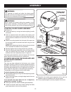
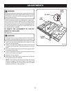
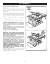
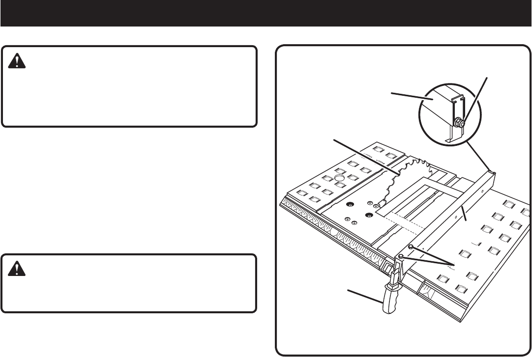
LOCKING
HANDLE
CLAMP
SCREW
RIP FENCE
SAW
BLADE
Fig. 33
WARNING:
Before performing any adjustment, make sure the tool is
unplugged from the power supply and the switch is in the
OFF position. Failure to heed this warning could result in
serious personal injury.
To avoid unnecessary setups and adjustments, a good prac-
tice is to check your setups carefully with a framing square
and make practice cuts in scrap wood before making finish
cuts in good workpieces. Do not start any adjustments until
you have checked with a square and made test cuts to be
sure adjustments are needed.
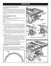
TO CHECK THE ALIGNMENT OF THE RIP
FENCE TO THE BLADE
See Figure 33.
WARNING:
To reduce the risk of injury, always make sure the rip fence
is parallel to the blade before beginning any operation.
Unlock the rip fence by depressing the trigger lock and
lifting the locking handle.
Place a framing square beside the blade and move the
rip fence up to the square. Take the dimension on the rip
scale.
Move the rip fence back and turn the framing square 180°
to check the other side.
If the two dimensions are not the same, loosen the two
screws on the fence and align it.
Retighten the two screws.
Make two or three test cuts on scrap wood. If the cuts
are not true, repeat the process.
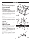
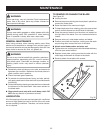
NOTE: The rip fence must be secure when the locking
handle is engaged. The clamp screw on the rear of the
rip fence is tightened by turning clockwise to increase
tightness of the rear of the rip fence.
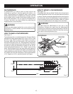
RIP
FENCE
SCREWS