Page 8
OPERATION
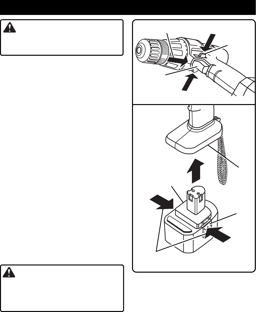
Fig. 5
Fig. 4
WARNING:
If any parts are missing, do not operate tool until the
missing parts are replaced. Failure to do so could result
in possible serious personal injury.
SWITCH
See Figure 4.
Your drill starts and stops by depressing and releasing the
switch trigger. Release the switch trigger to turn drill OFF.
VARIABLE SPEED
See Figure 4.
Your drill has a variable speed feature in the switch. The
switch delivers higher speed and torque with increased
trigger pressure. Speed is controlled by the amount of
switch trigger depression.
SWITCH LOCK
See Figure 4.
The switch trigger can be locked in the OFF position. This
feature helps reduce the possibility of accidental starting
when not in use. To lock the switch trigger, place the direction
of rotation selector in the center position.
TO INSTALL BATTERY PACK
■ Place the direction of rotation selector in center position.
See Figure 4.
■ Place the battery pack in your drill. Align raised rib on
battery pack with groove in drill's battery port.
See Fig-
ure 5.
■ Make sure the latches on each side of your battery pack
snap in place and that battery pack is secured in drill
before beginning operation.
TO REMOVE BATTERY PACK
■ Place the direction of rotation selector in center position.
See Figure 4.
■ Locate latches on side of battery pack and depress both
sides to release battery pack from your drill.
See Figure 5.
■ Remove battery pack from your drill.
CAUTION:
When placing battery pack in your drill, be sure raised
rib on battery pack aligns with groove in drill's battery
port and latches snap in place properly. Improper
assembly of battery pack can cause damage to internal
components.
DIRECTION OF
ROTATION
SELECTOR
SWITCH
TRIGGER
FORWARD
REVERSE
CENTER POSITION
(LOCK)
6
2
3
8
DEPRESS LATCHES TO
RELEASE BATTERY PACK
LATCHES
BATTERY
PACK
BATTERY
PORT


