11
Fig. 6
OPERATION
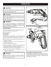
ADJUSTING TORQUE
See Figure 3.
There are twelve torque indicator settings located on the
front of the screwdriver.
Rotate adjustment ring to desired setting, aligning num-
ber on adjustment ring with arrow on housing.
• 1 - 2 For driving small screws
• 3 - 4 For driving screws into soft material
• 5 - 7 For driving screws into soft and hard
materials
• 8 - 9 For driving screws into hard wood
• 10 - 11 For driving large screws
• For full power applications
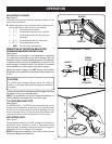
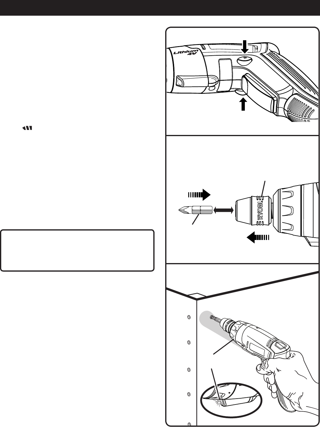
DIRECTION OF ROTATION SELECTOR
(FORWARD/REVERSE/CENTER LOCK)
See Figure 4.
The direction of bit rotation is reversible and is controlled
by a selector located above the switch trigger. With the
screwdriver held in normal operating position, the direction
of rotation selector should be positioned to the left of the
switch trigger for forward motion. The direction is reversed
when the selector is to the right of the switch trigger.
Setting the switch trigger in the OFF (center lock) position
helps reduce the possibility of accidental starting when not
in use.
CAUTION:
To prevent gear damage, always allow the collet to
come to a complete stop before changing the direction
of rotation.
To stop the screwdriver, release the switch trigger and allow
the collet to come to a complete stop.
NOTE: The screwdriver will not run unless the direction of
rotation selector is pushed fully to the left or right.
TO LOAD/RELEASE BITS
See Figure 5.
The SPEEDLOAD +™ SYSTEM on the screwdriver is a quick
change chuck designed to accept any 1/4 in. hex bits. Insert
the bit into the chuck and push as far as possible until the
chuck locks onto the bit. To remove a bit, push rubber collar
forward, and then pull the bit straight out of the chuck.
LED WORKLIGHT
See Figure 6.
The screwdriver has a built-in LED worklight. This feature is
convenient when working in close or tight areas where
additional light is needed. Whenever the switch trigger is
depressed, the LED worklight will illuminate.
NOTE: During normal operation, if the LED worklight will not
illuminate, charge the screwdriver.
Fig. 5
Fig. 4
FORWARD
REVERSE
LED
WORKLIGHT
BIT
L0AD BIT
RELEASE BIT
SPEEDLOAD +™ SYSTEM
RUBBER
COLLAR


