


17 — English
Fig. 17
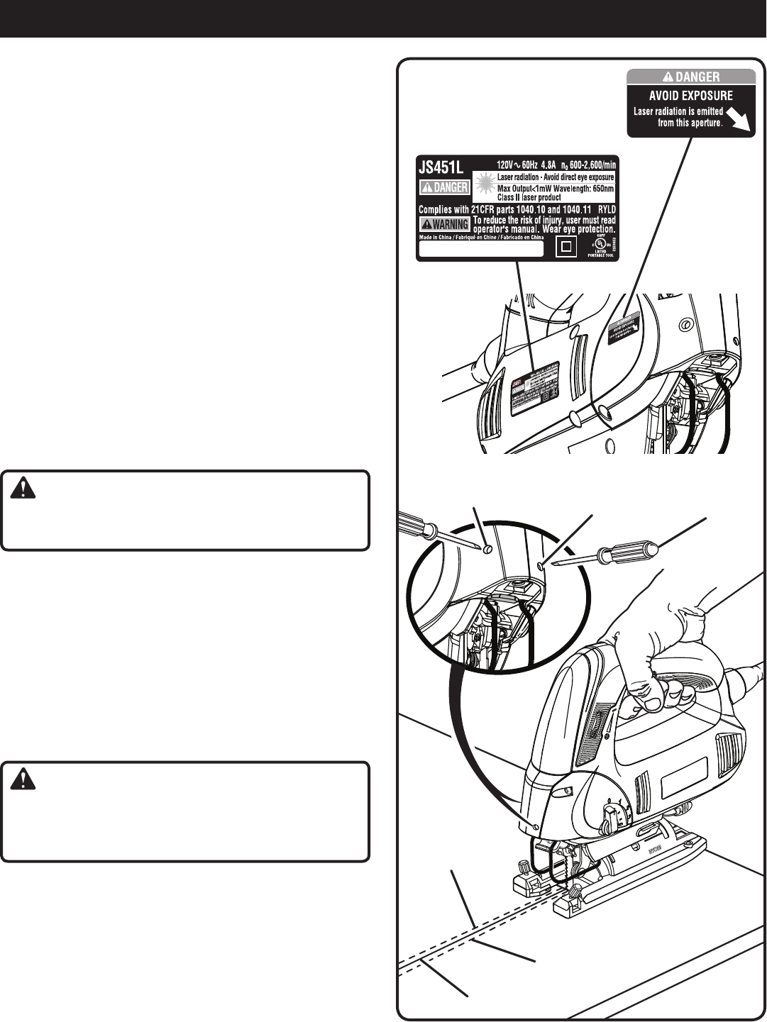
ADJUSTMENTS
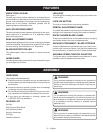
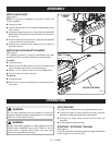
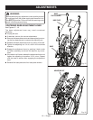
LASER GUIDE ADJUSTMENT
See Figure 17.
Draw a pencil line on a scrap workpiece. The line should
be approximately 12 inches long and should run all the
way to the edge of the workpiece.
Connect the jig saw to the power supply.
Align the blade of the jig saw with the pencil line on the
workpiece.
Depress the switch trigger and cut into the workpiece until
the base of the saw is fully supported by the workpiece
as shown. Once the cut is finished, do not allow the saw
to move throughout the rest of the adjustment process.
NOTE: Ignore the projected laser line during this cut.
Follow the pencil line visually to keep the blade cutting
along the pencil line.
Rotate the variable speed control selector to the lowest
speed possible.
Depress the switch trigger again to illuminate the laser.
Take note of the position of the laser line in relation to
the pencil line. If they are not together, unplug the jig saw
and perform adjustment steps below as needed until lines
come together.
WARNING:
Failure to unplug the saw could result in accidental start-
ing causing possible serious personal injury.
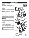
If the laser line is completely to the left of the pencil line,
turn the upper laser adjustment screw clockwise using a
small flat blade screwdriver. This will cause the laser line
to slide right.
If the laser line is completely to the right of the pencil line,
turn the upper laser adjustment screw counterclockwise.
This will cause the laser line to slide left.
If the laser line is twisted so that part of the line is to the
left of the pencil line and part of the line is to the right,
rotate the lower laser adjustment screw as necessary to
bring the two lines together.
WARNING:
Use of controls or adjustments or performance of pro-
cedures other than those specified herein could result in
hazardous radiation exposure.
lAsEr liNE
AT rigHT sidE
UppEr lAsEr
AdJUsTMENT
sCrEW
FlAT blAdE
sCrEWdriVEr
lAsEr liNE
AT lEFT sidE
pENCil liNE
loWEr lAsEr
AdJUsTMENT
sCrEW