


14 15
LO (1) SPEED
HI (2) SPEED
TWO SPEED
GEAR TRAIN
(HI-LO)
24
20
5
24
2 0
5
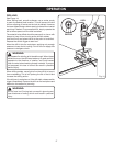
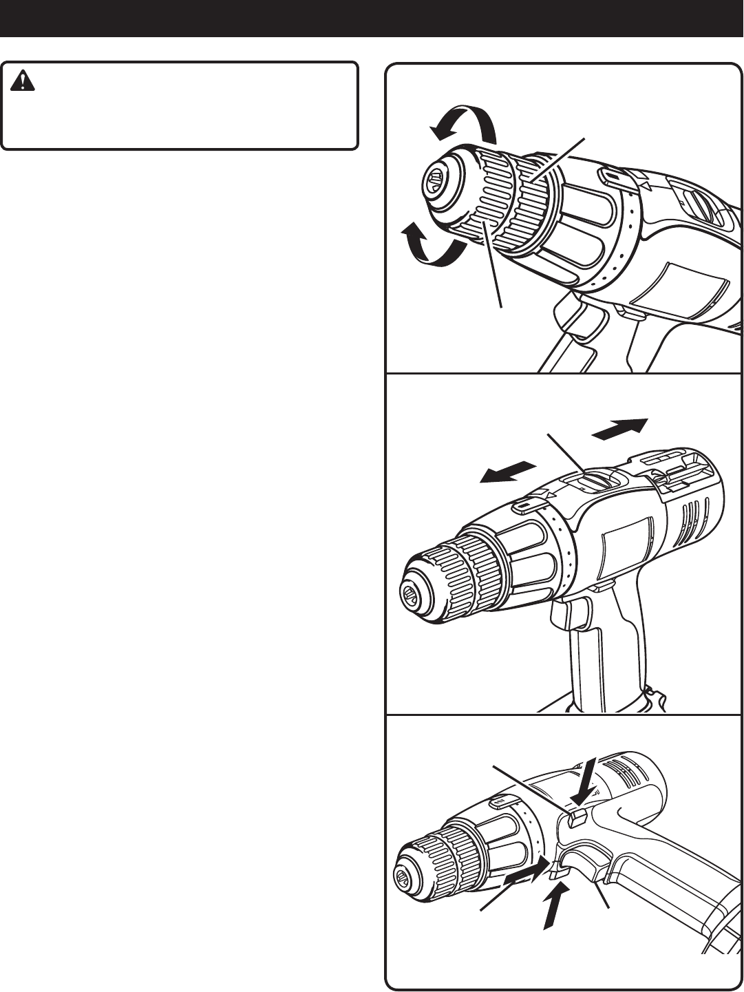
RELEASE
(UNLOCK)
GRIP
(TIGHTEN)
CHUCK
BODY
CHUCK COLLAR
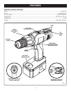
OPERATION
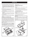
Fig. 7
Fig. 8
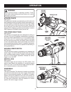
WARNING:
Battery tools are always in operating condition. There-
fore, switch should always be locked when not in use or
carrying at your side.
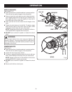
KEYLESS CHUCK
See Figure 7.
A keyless chuck has been provided with your drill to allow for
easy installation and removal of bits. As the name implies, you
can hand tighten or release drill bits in the chuck jaws. Grasp
and hold the collar of the chuck with one hand. Rotate the
chuck body with your other hand. The arrows on the chuck
indicate which direction to rotate the chuck body in order to
GRIP (tighten) or RELEASE (unlock) the drill bit.
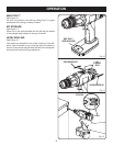
TWO SPEED GEAR TRAIN
See Figure 8.
The drill has a two-speed gear train designed for drilling or
driving at LO (1) or HI (2) speeds. A slide switch is located on
top of your drill to select either LO (1) or HI (2) speed. When
using drill in the LO (1) speed range, speed will decrease
and unit will have more power and torque. When using drill
in the HI (2) speed range, speed will increase and unit will
have less power and torque. Use LO (1) speed for high power
and torque applications and HI (2) speed for fast drilling or
driving applications.
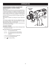
VARIABLE SPEED SWITCH
See Figure 9.
The drill starts and stops by depressing and releasing the
switch trigger. The switch delivers higher speed and torque
with increased trigger pressure. Speed is controlled by the
amount of switch trigger depression. Release the switch
trigger to turn drill OFF.
SWITCH LOCK
See Figure 9.
The switch trigger can be locked in the OFF position. This
feature helps reduce the possibility of accidental starting
when not in use. To lock the switch trigger, place the direc-
tion of rotation selector in the center position.
REVERSIBLE
See Figure 9.
This tool is reversible. The direction of rotation is controlled
by a selector located above the switch trigger. With the drill
held in normal operating position, the direction of rotation
selector should be positioned to the left of the switch for
drilling. The drilling direction is reversed when the selector
is to the right of the switch. When the selector is in center
position, the switch trigger is locked.
Fig. 9
24
20
5
SWITCH
TRIGGER
REVERSE
CENTER POSITION
(LOCK)
DIRECTION OF
ROTATION
SELECTOR