


12
OPERATION
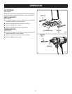
WARNING:
Battery tools are always in operating condition.
Therefore, switch should always be locked when not in
use or carrying at your side.
CAUTION:
The metal surface may become hot during use. Avoid
contact with it to avoid possible burn injury.
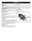
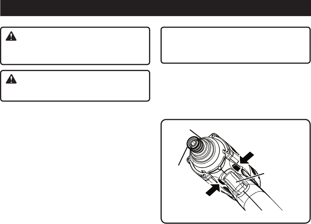
SWITCH TRIGGER
See Figure 4.
To turn the tool ON, depress the switch trigger. To turn it
OFF, release the switch trigger.
SWITCH LOCK
See Figure 4.
The switch trigger can be locked in the OFF (center)
position. This feature can be used to prevent the possibility
of accidental starting when not in use. To lock switch trigger,
place the direction of rotation selector in center position.
REVERSIBLE
See Figure 4.
This tool has the feature of being reversible. The direction of
rotation is controlled by a selector located above the switch
trigger. With the tool held in normal operating position, the
direction of rotation selector should be positioned to the left
of the switch for tightening. The direction is reversed when
the selector is to the right of the switch. When the selector
is in center position, the switch trigger is locked.
VARIABLE SPEED
See Figure 4.
This tool has a variable speed switch that delivers higher
speed and torque with increased trigger pressure. Speed is
controlled by the amount of switch trigger depression.
VARIABLE SPEED
SWITCH TRIGGER
FORWARD
REVERSE
Fig. 4
COUPLER
CAUTION:
To prevent gear damage, always allow coupler to come
to a complete stop before changing the direction of
rotation.
To stop, release switch trigger and allow the coupler to come
to a complete stop.
BUILT-IN COUPLER
See Figure 4.
The tool has a built-in coupler. The coupler has been de-
signed to accept 1/4 in. hex bits.
DIE CAST