


20 21
1
2
4
5
0
0
1
5
2
2
3
0
4
5
5
0
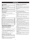
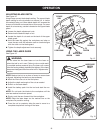
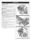
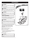
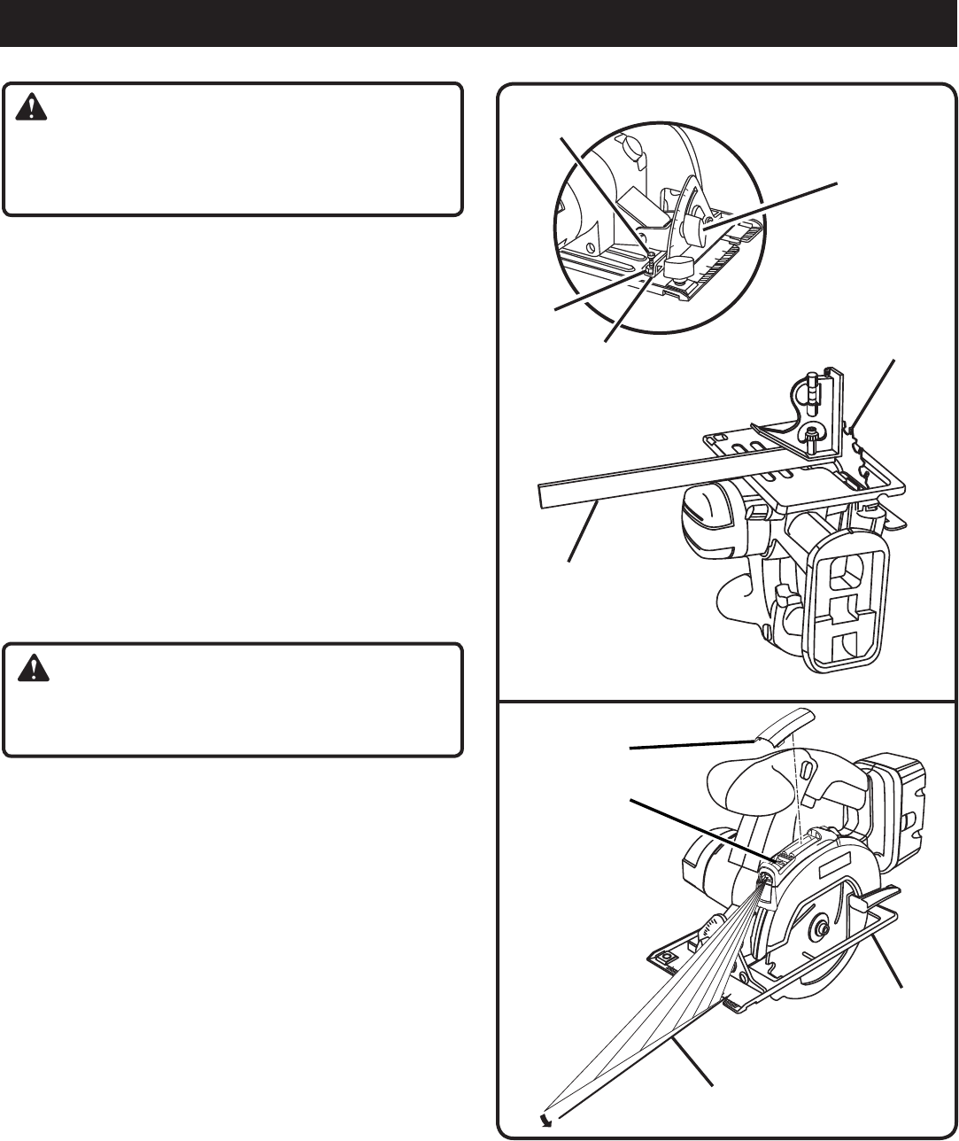
Fig. 24
BEVEL
ADJUSTMENT
KNOB
BLADE
CARPENTER'S
SQUARE
ADJUSTMENT
SCREW
HEX NUT
POSITIVE 0°
BEVEL STOP
ADJUSTMENTS
WARNING:
Before performing any adjustment, make sure the bat-
tery pack is removed from tool and the switch is in the
OFF position. Failure to heed this warning could result in
serious personal injury.
POSITIVE 0° BEVEL STOP
See Figure 24.
The saw has a positive 0° bevel stop that has been factory
adjusted to assure 0° angle of the saw blade when making
90° cuts.
CHECKING POSITIVE 0° BEVEL STOP
n Place the saw in an upside down position on a work-
bench.
n Check the squareness of the saw blade to the base of
the saw using a carpenter’s square.
ADJUSTING POSITIVE 0° BEVEL STOP
n Loosen bevel adjustment knob.
n Turn setscrew with hex key and adjust base until it is
square with the saw blade.
n Tighten bevel adjustment knob securely.
WARNING:
Attempting a bevel cut without having the bevel ad-
justment knob securely tightened can result in serious
injury.
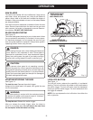
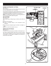
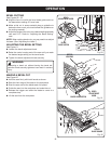
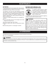
ADJUSTING THE LASER
See Figure 25.
�NOTE: Draw a pencil line on a scrap workpiece parallel to
the long edge of the base as a straight line guide to aid in
the adjusting process.
n Make sure the laser is turned off.
n Remove the laser cover by lifting it off its base.
�n Turn the laser on.
�n Loosen the screw inside the laser.
�n Rest the front of the base on a scrap workpiece.
n Adjust the laser beam with the mark on the scrap
workpiece by loosening the screw to the laser aperture
and slowly moving the laser guide left or right.
n Since blade thicknesses vary, always make a trial cut in
scrap workpiece to ensure an accurate cut.
�n Once alignment is achieved, tighten the screw.
�n Replace the laser cover.
n Check for proper alignment.
�n Repeat as necessary until the laser is aligned.
LASER
COVER
SCREW
Fig. 25
PENCIL
LINE
LONG EDGE
OF BASE