


10
4545
5050
3030
2222
1
1
2
3
0
45
ASSEMBLY
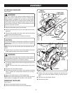
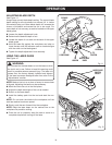
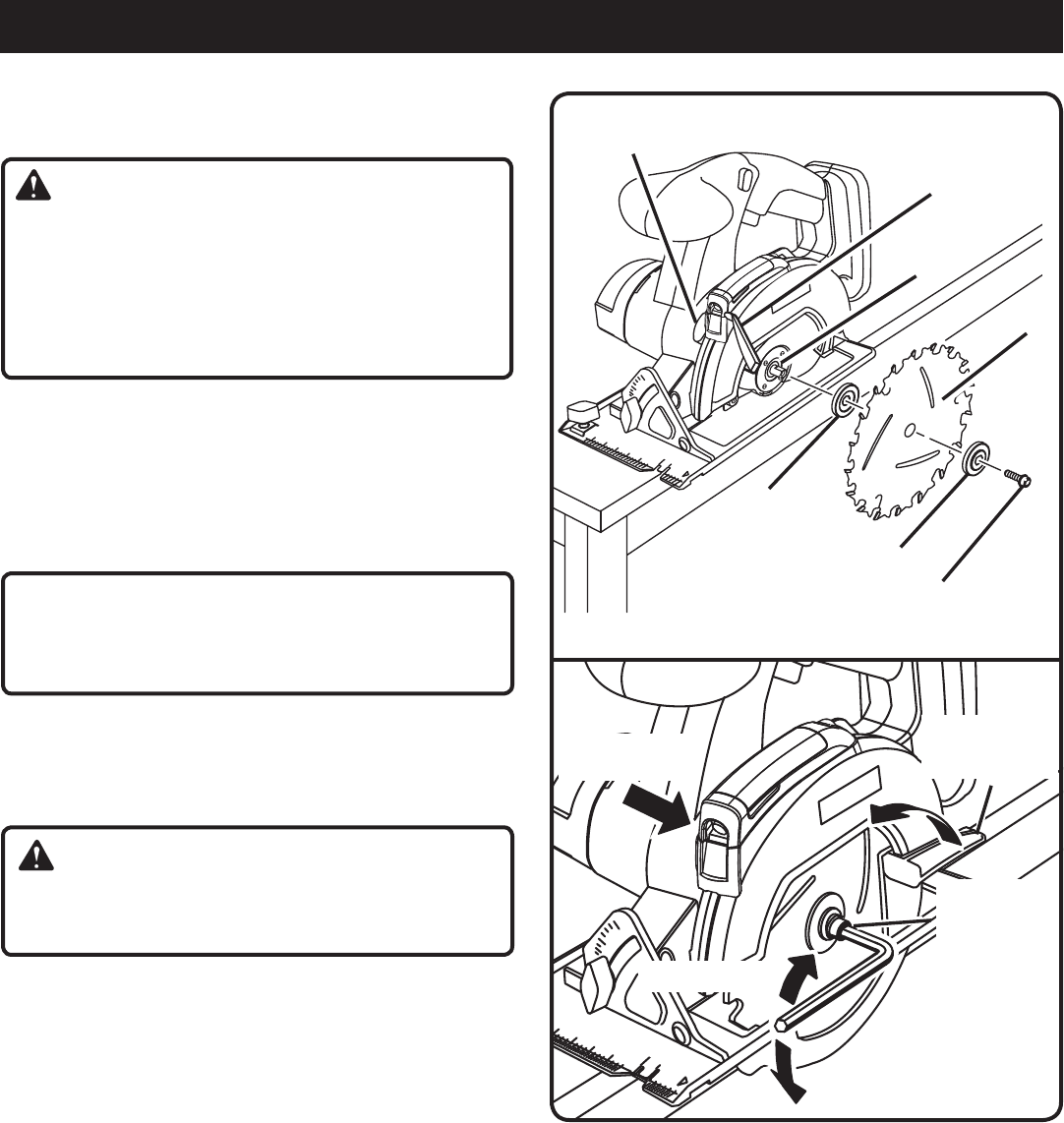
ATTACHING THE BLADE
See Figure 2.
WARNING:
A 5-1/2 in. blade is the maximum blade capacity of the
saw. Never use a blade that is too thick to allow outer
blade washer to engage with the flats on the spindle.
Larger blades will come in contact with the blade guard,
while thicker blades will prevent blade screw from se-
curing blade on spindle. Either of these situations could
result in a serious accident.
Remove the battery pack from the saw.
Remove the blade wrench (5 mm hex key) from the stor-
age area.
Depress the spindle lock button and remove the blade
screw and outer blade washer.
NOTE: Turn the blade screw clockwise to remove.
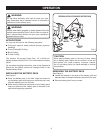
CAUTION:
To prevent damage to the spindle or spindle lock, always
allow motor to come to a complete stop before engaging
spindle lock.
NOTE: Do not run the circular saw with spindle lock en-
gaged.
Wipe a drop of oil onto the inner blade washer and outer
blade washer where they contact the blade.
WARNING:
If inner blade washer has been removed, replace it before
placing blade on spindle. Failure to do so could cause an
accident since blade will not tighten properly.
Fit the saw blade inside the lower blade guard and onto
the spindle.
NOTE: The saw teeth point upward at the front of the
saw.
Replace the outer blade washer.
Depress the spindle lock button, then replace the blade
screw. Tighten the blade screw securely by turning it
clockwise.
Return the blade wrench to the storage area.
NOTE: Never use a blade that is too thick to allow the outer
blade washer to engage with the flats on the spindle.
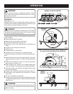
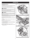
REMOVING THE BLADE
See Figure 3.
Remove the battery pack from the saw.
Remove the blade wrench from the storage area.
Fig. 2
INNER
BLADE WASHER
OUTER
BLADE WASHER
LOWER BLADE
GUARD HANDLE
BLADE SCREW
BLADE
SPINDLE
SPINDLE
LOCK BUTTON
Position the saw as shown, depress the spindle lock
button, and remove the blade screw by turning it clock-
wise.
Remove the outer blade washer.
Remove the blade.
Fig. 3
4545
5050
3030
2222
1
1
2
3
0
45
SPINDLE LOCK
TO LOOSEN
TO TIGHTEN
LOWER BLADE
GUARD LEVER
SPINDLE
LOCK
SCREW