


Page 8
WARNING:
Failure to unplug your router could result in accidental
starting causing serious injury.
CUTTER
INSIDE SUBBASE
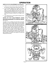
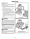
INSTALLING/REMOVING CUTTERS
(Continued)
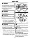
7. To use cutters with 1/4 in. (6.4 mm) shank bits, the 1/2
in. (13 mm) collet assembly must be removed and
replaced with the 1/4 in. (6.4 mm) collet assembly.
Remove the 1/2 in. (13 mm) collet assembly by
removing collet nut, loosening collet screw securing
collet to motor shaft, then removing collet assembly.
NOTE: The collet screw has left hand threads and you
will need a phillips screwdriver to loosen collet screw.
8. Replace with the 1/4 in. (6.4 mm) collet assembly,
securely tightening collet screw in collet to motor shaft,
then reassemble 1/2 in. (13 mm) collet nut.
See Figure 4.
9. Insert shank of cutter into collet until shank bottoms
out, then pull it out 1/16 in. (1.6 mm) to allow for
expansion when the bit gets hot.
10. Tighten the collet nut securely by turning clockwise
with the wrench provided.
See Figure 3.
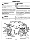
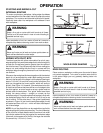
11. Place spindle lock back in unlock position. Otherwise,
interlocking mechanism of spindle lock will not let you
turn your router on. To unlock spindle, (1) push spindle
lock in, (2) slide into unlock position, then (3) release
spindle lock.
See Figure 2.
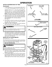
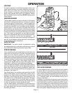
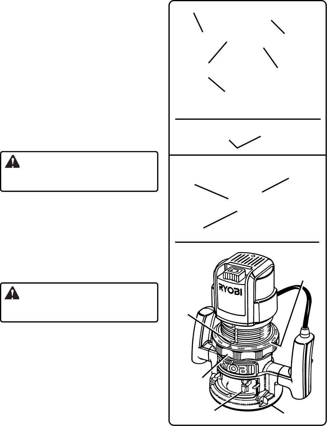
DEPTH OF CUT ADJUSTMENTS
See Figures 5, 6, 7, and 8.
We recommend that cuts be made at a depth not exceeding
1/8 in. (3.2 mm) and that several passes be made to reach
depths of cut greater than 1/8 in. (3.2 mm).
1. UNPLUG YOUR ROUTER.
2. Place your router on a flat surface, unlock clamping
lever, and turn depth adjusting ring until cutter is inside
subbase.
See Figure 5.
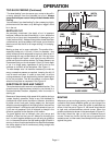
3. Turn the depth adjusting ring until tip of cutter touches
flat surface (zero depth of cut).
See Figure 6.
Next turn
depth indicator ring until the zero lines up with the
indicator point on front of motor housing.
See Figure 5.
MOTOR SHAFT
1/2 IN. (13 MM)
COLLET NUT
COLLET SCREW
(LEFT HAND THREADS)
1/2 IN. (13 MM)
COLLET ASSEMBLY
1/4 IN. (6.4 MM)
COLLET ASSEMBLY
DEPTH
INDICATOR
RING
INDICATOR
POINT
DEPTH
ADJUSTING
RING
Fig. 4
SUBBASE
Fig. 5
TO
LOCK
TO
UNLOCK
CLAMPING
LEVER
REAR VIEW OF ROUTER
OPERATION
WARNING:
If collet nut is not tightened securely, cutter may come out
during use causing serious personal injury.
CUTTER WITH 1/4 IN. (6.4 MM)
SHANK DIAMETER