


10
OPERATION
WARNING:
Never connect the router to power supply when you
are assembling parts, making adjustments, install-
ing or removing cutters, or when not in use. Discon-
necting the router prevents accidental starting that
could cause serious injury.
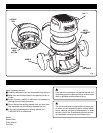
REMOVING AND INSTALLING THE ROUTER
BASE
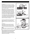
TO REMOVE THE ROUTER BASE
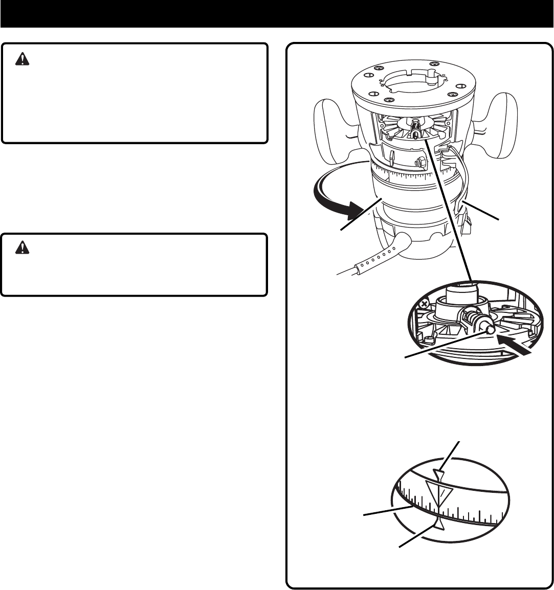
See Figure 4.
1. Unplug the router.
WARNING:
Failure to unplug the tool could result in accidental
starting causing serious injury.
2. Place the router upside down with the Ryobi label
away from you.
3. Loosen the locking arm on the base.
4. Depress and hold the spindle lock button on the motor.
5. Turn the collet nut until the hole in the collet aligns with
the spindle lock button.
6. Turn the depth adjusting ring counterclockwise until
the motor is to its highest position.
7. Align the indicator arrow on the depth adjustment ring
with the indicator point on the base.
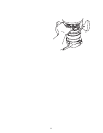
8. Pull the base until it dislodges from the motor housing.
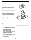
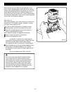
TO INSTALL THE ROUTER BASE
1. Unplug the router.
2. Place the fixed base on a flat surface.
3. Loosen the locking arm.
4. Align the indicator arrow on the depth adjustment ring
with the indicator point on the base.
5. Align the spindle lock button with the groove in the
base.
6. Depress and hold the spindle lock button on the motor.
7. Slide the motor housing into the base.
8. Turn the depth adjusting ring counterclockwise until
the spindle lock snaps out as it clears the rear window,
just below the locking arm.
9. Tighten the locking arm.
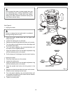
Fig. 4
LOCKING
ARM
DEPTH
ADJUSTMENT
RING
SPINDLE
LOCK
BUTTON
1
2
0
15/32
1/32
DEPTH
INDICATOR
RING
INDICATOR POINT
INDICATOR
ARROW