


Page 14
24
20
5
IMPORTANT INFORMATION FOR RECHARGING
HOT BATTERIES
When using your drill-driver continuously, the batteries in
your battery pack become hot. You should let a hot battery
pack cool down for approximately 30 minutes before at-
tempting to recharge.
Note: This situation occurs when continuous use of your
drill-driver causes the batteries to become hot. It does not
occur under normal circumstances. Refer to “Charging Your
Drill-Driver” earlier in this manual, for normal recharging of
batteries. If the charger/charging assembly does not charge
your battery pack under normal circumstances, return both
the battery pack and charger/charging assembly to your
nearest Ryobi Authorized Service Center for electrical
check.
For more information on the battery recycling call
1-800-8 BATTERY.
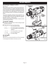
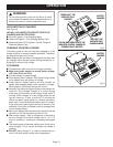
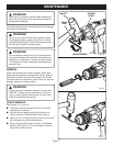
TO INSTALL BATTERY PACK
■■
■■
■ Place the direction of rotation selector in center posi-
tion.
See Figure 10.
■■
■■
■ Place the battery pack in your drill. Align raised rib on
battery pack with groove in drill's battery port.
See Fig-
ure 11.
■■
■■
■ Make sure the latches on each side of your battery pack
snap in place and that battery pack is secured in drill
before beginning operation.
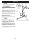
TO REMOVE BATTERY PACK
■■
■■
■ Place the direction of rotation selector in center posi-
tion.
See Figure 10.
■■
■■
■ Locate latches on side of battery pack and depress both
sides to release battery pack from your drill.
See Figure
11.
■■
■■
■ Remove battery pack from your drill.
CAUTION:
When placing battery pack in your drill, be sure raised
rib on battery pack aligns with groove in drill's battery
port and latches snap in place properly. Improper
assembly of battery pack can cause damage to inter-
nal components.
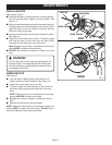
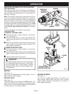
SWITCH
See Figure 10.
To turn your drill ON, depress the switch trigger. To turn it
OFF, release the switch trigger.
SWITCH LOCK
See Figure 10.
The switch trigger can be locked in the OFF position. This
feature helps reduce the possibility of accidental starting
when not in use. To lock the switch trigger, place the direction
of rotation selector in the center position.
Fig. 10
SWITCH
TRIGGER
FORWARD
REVERSE
CENTER POSITION
(LOCK)
DIRECTION OF
ROTATION
SELECTOR
Fig. 11
BATTERY
PACK
BATTERY
PORT
LATCHES
DEPRESS LATCHES TO
RELEASE BATTERY PACK
OPERATION
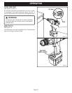
VARIABLE SPEED
See Figure 10.
Your drill has a variable speed feature in the switch. The
switch delivers higher speed and torque with increased
trigger pressure. Speed is controlled by the amount of
switch trigger depression.