


Page 17
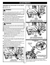
SQUARING THE SAW BLADE TO THE FENCE
See Figures 21 - 24.
■ Unplug your saw.
WARNING:
Failure to unplug your saw could result in accidental
starting causing possible serious personal injury.
■ If saw is mounted to a workbench, it must be unmounted
to square the saw blade to the fence.
■ Pull the saw arm all the way down and engage the lock pin
to hold the saw arm in transport position.
See Figure 3.
■ Place saw on a large, stable work surface.
■ Loosen the miter lock handle approximately one-half turn.
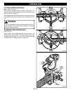
■ Position saw in tilted position as shown in figure 24, to
locate the two socket head screws under the miter table.
CAUTION:
To prevent loss of control of your saw, hold saw base with
one hand while loosening the socket head screws with
your other hand.
■ Using a 10 mm hex key, loosen the two socket head screws.
■ Reposition saw to its normal operating position.
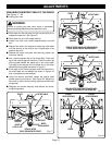
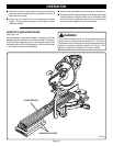
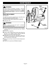
■ Lay a framing square flat on the miter table. Place one
leg of the square against the fence. Slide the other leg of
the square against the flat part of saw blade.
NOTE: Make sure that the square contacts the flat part
of the saw blade, not the blade teeth.
■ The edge of the square and the saw blade should be
parallel as shown in figure 21.
■ If the front or back edge of the saw blade angles away
from the square as shown in figures 22 and 23, adjust-
ments are needed.
■ Using the miter lock handle, move the miter table left or
right until the saw blade is parallel to the square.
■ Position saw in tilted position as shown in figure 24 and
tighten the two socket head screws securely.
■ Reposition saw to its normal operating position.
■ Recheck the fence-to-table alignment.
ADJUSTMENTS
NOTE: After squaring adjustments have been made, it
may be necessary to loosen the scale indicator screw and
reset the indicator to zero.
Fig. 22
FENCE
VIEW OF BLADE NOT SQUARE WITH
FENCE, ADJUSTMENTS ARE REQUIRED
FENCE
BLADE
FRAMING
SQUARE
BLADE
MITER
TABLE
MITER
TABLE
VIEW OF BLADE NOT SQUARE WITH
FENCE, ADJUSTMENTS ARE REQUIRED
FRAMING
SQUARE
SOCKET
HEAD SCREWS
MITER LOCK
HANDLE
BLADE
MITER
LOCK HANDLE
MITER
LOCK PLATE
FENCE
FRAMING
SQUARE
MITER
TABLE
VIEW OF BLADE
SQUARE WITH FENCE
Fig. 21
Fig. 23
SCALE
INDICATOR
SCALE INDICATOR
SCREW
Fig. 24
SAW BASE SHOWN TILTED
UP TO LOCATE SCREWS