


page 5
OPERATION
To reduce the risk of injury, wear safety goggles
or glasses with side shields.
WARNING!
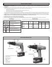
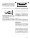
The torque specifications shown here are approximate values obtained
with a fully charged battery pack.
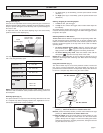
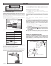
Using Clutch (Fig. 3)
This tool has an adjustable clutch for driving different types of screws into
different materials. When properly adjusted, the clutch will slip at a preset
torque to prevent driving the screw too deep and to prevent damage to
the screw or tool.
To adjust the clutch, turn the clutch adjusting ring to one of the twenty
positions shown on the adjusting ring.
NOTE: Because the above settings are only a guide, use a piece of scrap
material to test the different clutch positions before driving screws into
the workpiece.
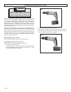
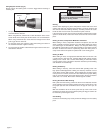
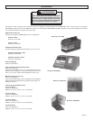
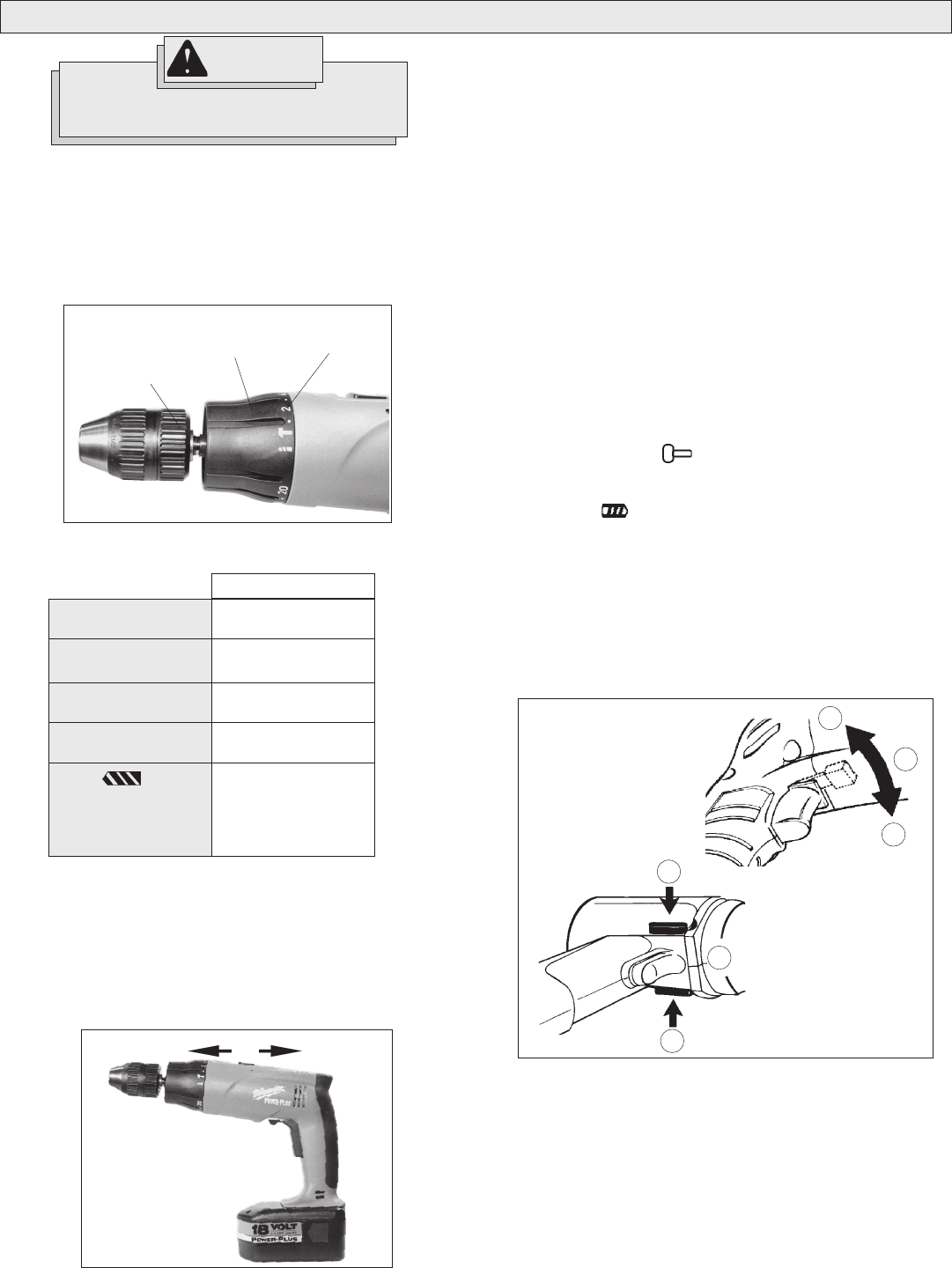
Selecting Speed (Fig. 4)
The speed selector is on top of the motor housing. Allow the tool to come
to a complete stop before changing speeds. See “Applications” for rec-
ommended speeds under various conditions.
1. For Low speed (up to 500 RPM), push the speed selector forward
(Position 1).
2. For High speed (up to 1600 RPM), push the speed selector back
(Position 2).
Starting, Stopping & Controlling Speed
1. To start the tool, pull the trigger.
2. To stop the tool, release the trigger and an electric brake stops the
tool instantly.
All models feature variable speed control. To vary the speed, simply in-
crease or decrease pressure on the trigger. The further the trigger is pulled,
the greater the speed.
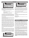
Selecting Hammer or Drill Action
MILWAUKEE
Hammer-Drills are designed for two operating modes: drill-
ing with hammering action and drilling only. To set the operating mode,
rotate the Hammer-Drill selector collar to the desired symbol. A drill or
hammer symbol will appear at the top center of the collar to indicate
operating mode.
1. To use the hammer-drilling mode, rotate the selector collar until
the hammer symbol appears at the top center of the collar.
Apply pressure to the bit to engage the hammering mechanism.
2. To use the drilling only mode, rotate the selector collar until the
drill symbol appears at the top center of the collar.
NOTE: When using carbide bits, do not use water to settle dust. Do not
attempt to drill through steel reinforcing rods. Both actions will damage
the carbide bits.
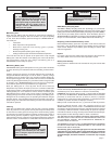
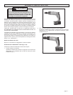
Using Control Switch (Fig. 5)
The control switch may be set to three positions: forward, reverse and
lock. Due to a lockout mechanism, the control switch can only be ad-
justed when the ON/OFF switch is not depressed. Always allow the motor
to come to a complete stop before using the control switch.
Forward (clockwise) rotation, push the control switch to the left
position (1). Check the direction of rotation before use.
Reverse (counter clockwise) rotation, push the control switch to the right
position (2). Check direction of rotation before use.
Locking the trigger, push the control switch to center position (3). The
trigger will not work while the control switch is in the center locked
position. Always lock the trigger or remove the battery pack before
performing maintenance, changing accessories, storing the tool and
any time the tool is not in use.
Positions 1 - 5
Positions 6 - 10
Positions 11 - 15
Positions 16 - 20
Drill
Low
High
0 - 14 in. lbs.
20 - 41 in. lbs.
46 - 60 in. lbs.
65 - 85 in. lbs.
400 in. lbs.
120 in. lbs.
Torque
Fig. 3
Clutch
Adjusting Ring
Position
Numbers
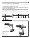
Hammer-drill
selector collar
Fig. 5
2
1
3
3
1
2
Cat. No. 0523-20
Cat. No. 0524-20
Fig. 4
Low High