


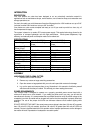

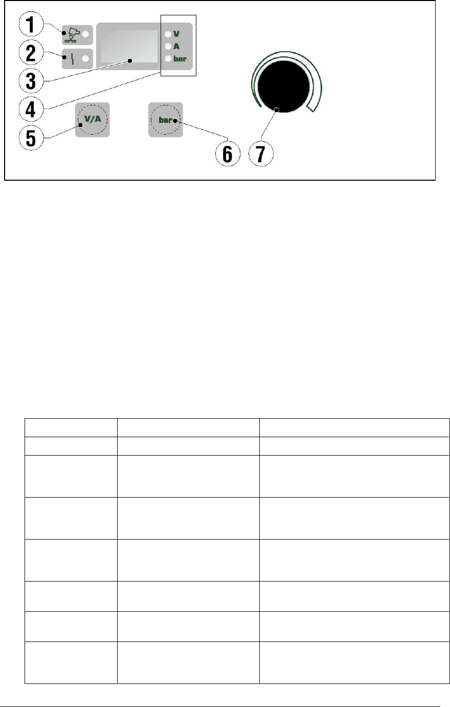
CONTROLS & THEIR FUNCTIONS
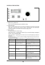
1. POWER OUTPUT INDICATOR
When lit, this LED indicates that power is available for cutting.
2. ALARM INDICATOR
When lit, this LED indicates that one of the alarms has triggered. At the same time the digital
display (Ref. 3) shows the type of alarm, as shown in the table below, with instructions\for
correcting the problem. In this condition the unit does not supply current.
3. DIGITAL DISPLAY
This display operates in a number of ways:
Display Volts or Amps – by pressing the V/A switch (5), you can read the voltage or amperage at
the torch. This is a momentary display
Display Air Pressure – By pressing the bar switch (6) you can read the operating air pressure of
they system.
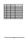
Error/Alarm Indications – If an error is present, the display will light showing the code of the error.
The codes are shown below:
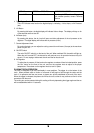
DISPLAY ERROR or PROBLEM CORRECTION/RESET
- - -
Insufficient input voltage
CUP
The nozzle cap is not properly
screwed on the torch
Turn the unit OFF. Tighten the nozzle
cap on the torch correctly and turn the
unit back ON
HtA
Unit is overheating Stop cutting – allow the unit to cool down.
Alarm will reset after the unit has cooled
down.
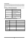
ThA (Flashing)
Unit is approaching
overheating
Stop cutting – allow the unit to cool down.
Alarm will reset after the unit has cooled
down.
Air
Insufficient air pressure Adjust air regulator to increase pressure.
Check incoming air line.
ScA
Short circuit in output of unit Turn the unit OFF and turn back ON to
reset
LSF
Arc blow out Check wear on electrode and nozzle.
Replace if worn. If alarm continues, cycle
the unit off and on.
15