


4
Sch555 English 10/30/97
G.
METER FUNCTIONS
PERCENT OF CHARGE
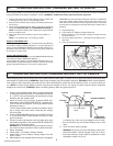
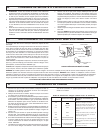
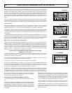
The percent of charge scale is intended as a visual aid to help simplify detemmining the state of
charge. It is scaled for use with the 6 or 10 amp charge rates only. For the 2 amp charge rate, use
the red triangle.The percent of charge is based on current draw by the battery. For this reason
accuracy will vary with the size and battery type. Typically a 28 ampere hour battery will draw less
current at end charge than a 140 ampere hour wet cell battery. This means that the indication for
a fully charged large battery may be slightly less than 100%.
For the 2 amp charge rate a red triangle has been provided within the green area of the meter
scale. It’s accuracy has been calibrated for use with small battery. As a battery takes on a charge,
correspondingly less of the red area will fall under the meter needle.
The Ammeter
The ammeter indicates the amp draw on the charger when a fully discharged battery is connected
to the charger. The meter will read the maximum output rating of the charger 2 amps, 10 amps, or
30 amps depending on the charger and switch position you have chosen.
The charge on the 2 amp or the 10 amp, will gradually taper down as the battery nears full charge.
As the charge current tapers, the ammeter needle will also move down. The 2 amp charge
produces such a small current that it will not show up very well on the meter.
The 30 amp boost charge (on the SF 1250 only) may be used for a quick charge prior to using the
engine start feature. The meter will indicate around the 30 amps line if the battery is fully dis-
charged and less if the battery is partially charged. Follow duty cycle instructions for this boost
position.
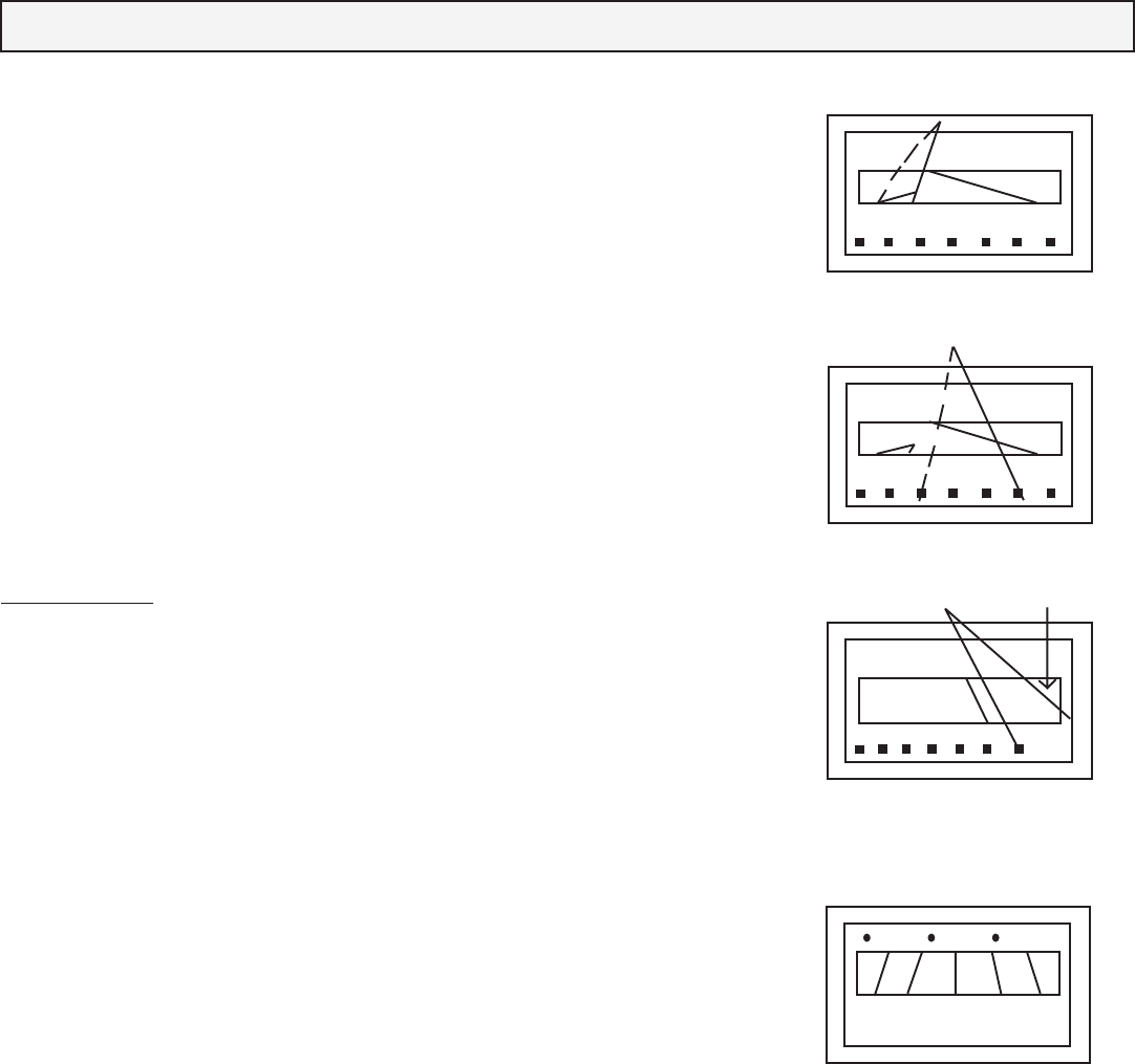
See Meter Views
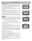
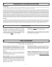
The charger meter needle will indicate somewhere between the solid line and the dotted line when
the charging is first started. The variation is due to the difference in battery conditions and con-
struction of the battery. A battery that is not fully charged will not require the charger to begin the
charge at the highest rating, such as the 10 amp on the 10 amp charge position. The battery is
charged when the meter indicates near the dotted line shown in the view at the right. This is about
1/2 of the selected charge rate. (about 4-5 amps on the 10 amp setting).
USING THE METER AS A BATTERY TESTER (Model SF 60 only)
1. Since this test is based on terminal voltage of the battery, always begin with fully charged
battery. The Battery must be in the vehicle, with the engine and accessories turned off.
2. There is no need for the charger to be connected to the AC power. Unplug charger or rotate timer
to the OFF position prior to testing.
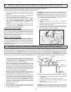
3. Connect charger to battery as described in Paragraph G.
4.The meter pointer should be within the green zone of the scale designated BATTERY. It the
battery has just been charged, the pointer may be past the green zone and into the yellow zone of
ALTERNATOR scale. This is normal. If the pointer rests in the red or yellow zone of the BATTERY
scale, the battery may need to be charged.
5. While connected to the battery, turn on the vehicle headlights. Leave on for approximately 10
minutes, then observe the meter reading. For a good battery, the pointer will initially move towards
the yellow side of the green zone, then remain fairly constant throughout remainder of the test. If
the pointer continues to move and falls into the yellow or red zone, the battery is either weak or
poor. For heavy duty batteries more accurate results may be obtained by extending the discharge
time a few minutes.
CHECKING THE VEHICLE CHARGING SYSTEM
1. Follow instructions 1 through 4 of battery test section (K).
2. Start engine. If the vehicle charging system is working properly, the meter pointer should be
within the green zone of the scale designated ALTERNATOR. If the pointer is in the yellow zone, it’s
likely that the alternator is not charging the battery. If the pointer rises to the extreme right hand side
of the red zone it’s likely that the battery is being overcharged.
NOTE - In order to compensate for the battery’s characteristics with temperature, the vehicle’s
charging system will increase its output voltage with a decrease in ambient temperature. The test
meter is calibrated for batteries at 25 C, as a result the meter indication will be slightly higher at
lower outside temperatures.
Before replacing the battery or components of your charging system, obtain a second opinion from
a professional. CAUTION - For maximum charger life and least annoyance by breaker cycling, use
start position for engine cranking only.
DC AMPS
0 2 4 6 8 10 12
CHARGE % 100 75 50 25 0
2 AMP RATE
2 amp
DC AMPS
2 AMP RATE
0 2 4 6 8 10 12
CHARGE % 100 75 50 25 0
10 amp
DC AMPS
0 5 10 15 20 25 30
30 amp
Engine Start
CHARGING
START
BATTERY
TESTER
CHARGER\
ALTERNATOR
POOR WEAK GOOD
R
Y
Gn
YGnR
Voltimeter