


3
2. Stay clear of fan blades, belts, pulleys, and other parts that can cause injury to persons.
3. Check polarity of battery posts. POSITIVE (POS, P. +) battery post usually has larger
diameter than NEGATIVE (NEG, N. -) post.
4. Determine which post of battery is grounded (connected) to the chassis. If negative post
is grounded to chassis (as in most vehicles), see #5. If positive post is grounded to the
chassis, see #6.
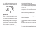
5. For negative-grounded vehicle, connect POSITIVE (RED) clip from battery charger to
POSITIVE (POS, P. +) ungrounded post of battery. Connect NEGATIVE (BLACK) clip to
vehicle chassis or engine block away from battery. Do not connect clip to carburetor, fuel
lines, or sheet-metal body parts. Connect to a heavy gage metal part of the frame or engine
block.
6. For positive-grounded vehicle connect NEGATIVE (BLACK) clip from battery charger to
NEGATIVE (NEG, N. -) ungrounded post of banery. Connect POSITIVE (RED) clip to
vehicle chassis or engine block away from battery. Do not connect clip to carburetor, fuel
lines, or sheet-metal body parts. Connect to a heavy gage metal part of the frame
or engine block.
7. When disconnecting charger, turn switches to off, disconnect AC cord, remove clip from
vehicle chassis, and then remove clip from battery terminal, in that order.
8. See operating instructions for length of charge information.
H. FOLLOW THESE STEPS WHEN BATTERY IS OUTSIDE VEHICLE. A SPARK NEAR
THE BATTERY MAY CAUSE BATTERY EXPLOSION. TO REDUCE RISK OF A SPARK
NEAR BATTERY:
1. Check polarity of battery posts. POSITIVE (POS, P. +) battery post usually has a larger
diameter than NEGATIVE (NEG, N. -) post.
2. attach at least a 24 inch-long 6-gauge (AWG) insulated battery cable to NEGATIVE
(NEG, N. -) battery post.
3. Connect POSITIVE (RED) charger clip to POSITIVE (POS, P. +) post of battery.
4. Position yourself and free end of cable as far away from battery as possible - then con-
nect NEGATIVE (BLACK) charger clip to free end of cable.
5. Do not face battery when making final connection.
6. When disconnecting charger, always do so in reverse sequence of connecting proce-
dure and break first connection while as far away from battery as practical.
7. A marine (boat) battery must be removed and charged on shore. To charge it on board
requires equipment specially designed for marine use.
I. GROUNDING AND AC POWER CORD CONNECTION INSTRUCTIONS
Charger should be grounded to reduce risk of electric shock. Charger is equipped with an
electric cord having an equipment-grounding conductor and a grounding plug. The plug
must be plugged into an outlet that is properly installed and grounded in accordance with all
local codes and ordinances.
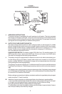
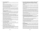
DANGER - Never alter AC cord or plug provided - if it will not fit outlet, have proper outlet
installed by a qualified electrician. Improper connection can result in a risk of an electric
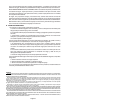
shock. This battery charger is for use on a nominal 120-volt circuit and has a grounding
plug that looks like the plug illustrated in sketch A in figure 1. A temporary adapter, which
looks like the adapter illustrated in sketches B and C, may be used to connect this plug to a
two-pole receptacle as shown in sketch B if a properly grounded outlet is not available. The
temporary adapter should be used only until a properly grounded outlet can be installed by
a qualified electrician.
DANGER - Before using adapter as illustrated, be certain that center screw of outlet plate
is grounded. The green colored rigid ear or lug extending from adapter must be connected
to a properly grounded outlet - make certain it is grounded. If necessary, replace original
outlet cover plate screw with a longer screw that will secure adapter ear or lug to outlet cover
plate and make ground connection to grounded outlet.
Use of an adapter is not allowed in Canada. If a grounding type receptacle is not available,
do not use this appliance until the proper outlet is installed by a qualified electrician.