


4
A SPARK NEAR BATTERY MAY CAUSE BATTERY EX-
PLOSION TO REDUCE RISK OF SPARK NEAR BATTERY:
1. Position AC and DC cords to reduce risk of damage by
hood, door, or moving engine part.
2. Stay clear of fan blades, belts, pulleys, and other parts
that can cause injury to persons.
3. Check polarity of battery posts. POSITIVE (POS, P,+)
battery post usually has larger diameter than NEGA-
TIVE (NEG, N, -) post.
4. Determine which post of battery is grounded (connected
to the chassis). If negative post is grounded to chassis
(as in most vehicles), see No. 5. If positive post is
grounded to the chassis, see No. 6.
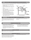
5. For a negative-grounded vehicle, connect POSITIVE
(RED) clip from battery charger to POSITIVE (POS,
P,+) ungrounded post of battery. Connect NEGATIVE
(BLACK) clip to vehicle chassis or engine block away
from battery. Do not connect clip to carburetor, fuel
lines, or sheet-metal body parts. Connect to a heavy
gage metal part of the frame or engine block.
6. For a positive-grounded vehicle, connect NEGATIVE
(BLACK) clip from battery charger to NEGATIVE (NEG,
N, -) ungrounded post of battery. Connect POSITIVE
(RED) clip to vehicle chassis or engine block away from
battery. Do not connect clip to carburetor, fuel lines, or
sheet-mebl body parts. Connect to a heavy gage metal
part of the frame or engine block.
7. When disconnecting charger, disconnect AC cord,
remove clip from vehicle chassis, and then remove clip
from battery terminal, in that order.
8. See charge period for length of charge information.
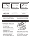
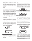
FOLLOW THESE STEPS WHEN BATTERY IS INSTALLED IN VEHICLE
GROUND
(NEG)
FIGURE 7 CONNECTION TO NEGATIVE
GROUNDED BATTERY
DC CONNECTION PRECAUTIONS
2. Attach clips to battery posts and twist or rock back and
forth several times to make a good connections This
tends to keep clips from slipping off terminals and helps
to reduce risk of sparking.
1. Connect and disconnect DC output clips only after
setting any charger switches to 2 AMP position and then
removing AC cord from electric outlet. Never allow clips
to touch each other.
G.
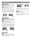
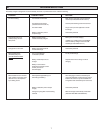
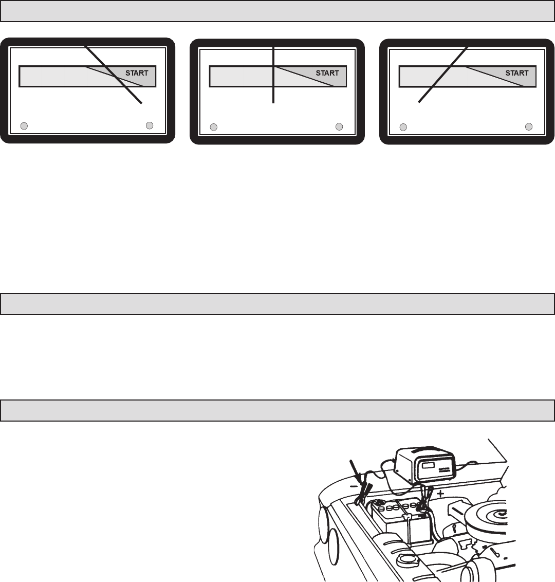
READING METER/LECTURA DEL MEDIDOR:
H.
I.
(SE-520MA has one LED, Full Charge)
POWER ONFULL CHARGE POWER ONFULL CHARGE
POWER ONFULL CHARGE
CHARGE % 100 75 50 25 0
CHARGE % 100 75 50 25 0 CHARGE % 100 75 50 25 0
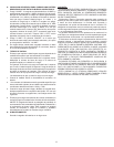
APPROACHES FULL CHARGE
Charge current to the battery is
typically 5 amps. The needle points
toward the 100% mark.
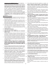
FULLY DISCHARGED BATTERY
Initial charge current to the battery is
typically 10 amps. The needle points
toward the 25% mark.
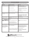
FULLY CHARGED BATTERY
Charge current to the battery is 0
amps. And, the Full Charge
green LED glows. The needle points
toward the Full Charge LED.
BATERIA TOTALMENTE DESCARGADA
La corriente de carga inicial a la batería es
típicanmente de 10 Amperios.
La aguja apunta hacia la marca de 25%.
(SE-520MA Porta una señal LED,
de carga completa)
ACERCANDOSE A PLENA CARGA
La corriente de carga a la batería es
típicamente de 5 Amperios.
La aguja apunta hacia la marca de 100%
BATERIA A PLENA CARGA
La corriente de carga a labatería es de 0
amperios y la LED verde se enciende. La
aguja apunta hacia la luz verde
de carga completa.