


4
Sch487
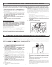
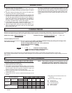
H. OUTPUT SELECTOR CONTROLS
Switches
Select
down
12v 40A
up
12v 2A
#
1
#
2
#
3
12v 200A
Start
6v 40A
or
6v 100A
Start
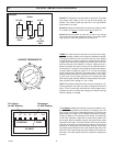
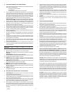
CHARGING START
DC AMPS
0 10203040 200
Discharged
40 AMP Reading
TIMER: The main function of the timer is to prevent over charg-
ing while allowing a battery time to obtain a satisfactory charge.
To properly set the timer you must know the size of the battery
in ampere hours or reserve capacity in minutes and the state of
charge. Often the state of charge is not known, this is one rea-
son why the timer was limited to 2.5 hours. With the aid of a
battery load tester the state of charge can be obtained within a
few seconds. For example, the average size automotive battery
at a 50% state of charge will require 1 to 1.5 hours of charging
at the 40 amp rate to reach the full charge state. For the same
battery with the timer set to it’s maximum, 2.5 hours, over charg-
ing will occur, but not likely cause harm to a battery that was
other wise in good condition. When the charge state is not known,
start out with a timer setting of 1 hour or less.
HOLD This position defeats the timer function, allowing for con-
tinuous operation. Use when you want to charge more than 2.5
hours. This is normally the case when the 2 amp charge rate is
selected. Be sure to monitor the charging and stop the charge
when the battery is charged.
Full Charge
40 AMP Reading
The Ammeter indicates the amount of current measured in am-
peres that is being drawn by the battery. For example, In the 40
amp charge rate a typical discharged battery will initially draw
approximately 40 amps. As the battery continues to charge,
current will taper to 15 to 20 amps at full charge. The Start area
of the meter indicates a high rate of current being drawn from
the charger. When cranking an engine, the starter motor draws
upwards to 200 amps. The meter needle will be at the extreme
right side of the start area. Sometimes a battery for the first few
minutes of it’s charge will draw more than 40 amps, in this case
the needle may be within but not to the extreme right side of the
start area. The 2 amp charge rate may indicate some activity on
the meter. The meter doesn’t have the resolution to display this
low rate.
Switch #1 Furthest left, Use this switch to select the 12volt 200
amp engine start (down) or the 12 volt 40 amp charge (up)
position. The center switch (#2) must be in the (up) position
when switch #1 is used.
Switch #2 (Center) Use this switch to select use of either switch
#1 or switch #3.
Down for switch #3 and up for switch #1.
Switch #3 Use this switch to select the 12 volt 2 amp charge
(up) or the 6 volt 100 amp engine start (down). The center switch
(#2) must be in the down position to use switch #3.
CHARGE TIME/MINUTES