


3
G. DC CONNECTION PROCEDURE
Whenchargingbattery(ies)inboat,takecaretodeterminethebatterytypeandwhichpoleisground.Toreduceriskofasparknear
battery, follow these general steps when battery is inside boat. WARNING: Asparknearthebatterymaycausebatteryexplosion.
1. PositionACpowercordandDCchargingcordstoreducerisk
of damage.
2. Stay clear of fan blades, belts, pulleys, and other parts that
can cause injury.
3. Checkpolarityofbatteryposts.Batterycasewillbemarked
toindicateeachpost’spolarity:POSITIVE(POS,P,+)and
NEGATIVE(NEG,N,-).NOTE: The positive battery post
usually has a larger diameter than the negative post.
4. Determine which post of battery is ground.
5. ConnectPOSITIVE(RED)ringterminalfrombatterycharger
toPOSITIVE(POS,P,+)postofbattery.
6. ConnectNEGATIVE(BLACK)ringterminaltoNEGATIVE
(NEG,N,-)postofbattery
7. Whendisconnectingthecharger,disconnecttheACpower
cordfromtheelectricoutletrst.
8. While disconnecting output leads from the batteries, always
do so in reverse order of the connection procedure.
H. DC WIRING DETAILS
When connecting the ring terminals to the battery, remove nuts
on battery posts, place the ring terminal on corresponding posi-
tive and negative post, and replace each nut tightly to ensure a
good connection.
When connecting the ring terminals, connect the black 12 volt
lead to the negative battery post and the red 12 volt lead to the
positive battery post.
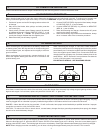
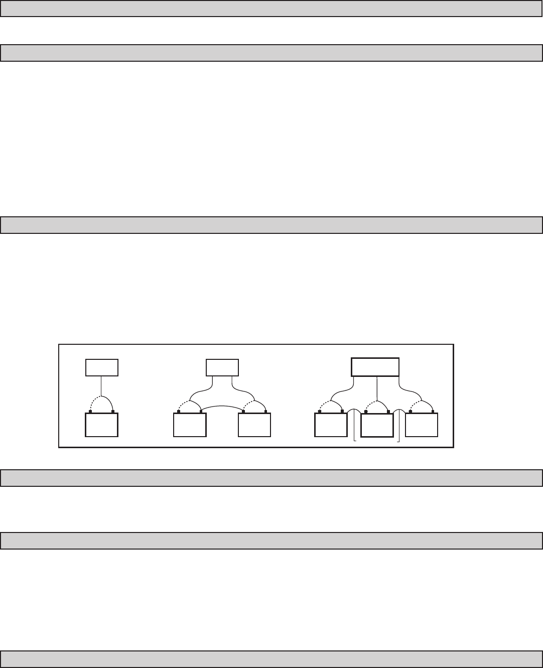
WhenconnectingthechargertoTWOandTHREEbatteries,
connect the positive lead from charging bank one to the positive
postofbatteryone.Connectthenegativeleadfromchargingbank
onetothenegativepostofbatteryone.Connecttheleadsfrom
charging bank two to battery two, and three to battery three in the
samefashion,.NOTE:Removal of a strap between two batteries
in a 24 or 36 Volt system is not necessary.
FOR DETAILED WIRING – SEE DIAGRAMS BELOW
12V
1 Battery
12V
+
–
+
–
12V
+
–
12V
+
–
12V
+
–
12V
+
–
12V
12V
2 Batteries
12V
3 BATTERIES
STRAPS OPTIONAL
STRAP
OPTIONAL
I. INLINE FUSES
Inline fuses, located close to the ends of the red leads, protect the charger from extremely high voltage surges, lightning strikes or other
highcurrentsurges.Ifafuseblows,replaceonlywithAGC-3030A32V1¼”glassfuse.
J. GROUNDING AND AC POWER CORD CONNECTION INSTRUCTIONS
Chargershouldbegroundedtoreduceriskofelectricshock.Chargerisequippedwithanelectriccordhavingagroundingplug.Theplug
must be plugged into an outlet that is properly installed and grounded in accordance with all local codes and ordinances.
DANGER–NeveralterACcordorplugprovided–ifitwillnottoutlet,haveproperoutletinstalledbyaqualiedelectrician.Improper
connection can result in a risk of an electric shock.
CAUTION–Toreduceriskofreorelectricshock,connectbatterychargerdirectlytogroundingreceptacle(three-prong).Anadapter
should not be used with battery charger.
K. OPERATING INSTRUCTIONS
F. DC CONNECTION PRECAUTION
ConnectanddisconnecttheDCoutputconnectionsonlyafterremovingtheACcordfromtheelectricoutlet.
Oncetheunithasbeenproperlyconnectedtothebattery(ies),pluginthechargertoACpower.HoldtheSETbuttonfortwoseconds.
Whenthebluelightturnson,presstheSELECTbuttonuntilthecorrectbatterytypecolorisblinking.Oncethecorrectbatterytypeis
blinkingpresstheSETbutton.Theblinkinglightwillmovetonextbattery.Greenlightindicateswhenbattery(ies)is/arefullycharged.
NOTE:Whenchargingmorethanonebattery,youwillhearaclickingnoiseapproximatelyeveryveminutes.Thisisnormal.