


Assembly
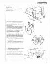
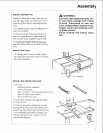
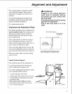
9. Push slide arm supports until "L" brack-
ets are flush with saw frame, then attach:
use one V2"long truss head screw per sup-
port (insert screw through "L" bracket); on
end of each screw put 17/d' in. diam x 9h6
out. diam flat washer, then lock washer,
then nut and wrench tighten.
10. From underneath table, tighten pan
head screws in each slide arm support.
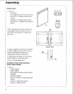
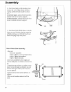
Assemble Table Lock Mechanism
L
1. Set out:
-two siide arms
-two spacers
-two v4" diam x lye" long pan head screws
-two 14" diam x s_" long pan head screws
-six wd' in. diam x _46out. diam flat
washers
-two v4" diam lock washers
-two v4" diam hex nuts
-two v4" diam square lock nuts.
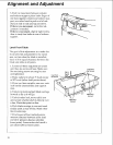
2. Snap spacer into each slide arm.
÷
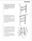
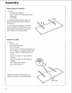
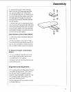
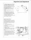
3. Drop slide arm into each slide arm sup-
port so "nose" faces front of table and
"arm" extends over lock handle channel.
Fronl
Of Saw
32