


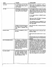
It may be necessary to brace or support one
end of the outfit when attaching the wheels
and the foot extension bracket because the
outfit will have a tendency to tip over before
wheels are attached.
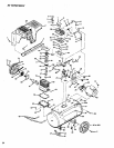
1. Insert the handle into pockets under the tank Saddle;
Put one set screw (28) through holein one side oftank
saddle and tighten down on handle.
2. Remove the protective paper strip from the adhesive
backed rubber foot strip (47). Attach the rubber foot
strip to the bottom of the foot extension bracket (45).
Press firmly into place.
3. Attach foot extension bracket (45) to the air tank
bracket. Use one cap screw (46) one Iockwasber (83)
and one hex nut (44) at each end. Tighten.
4, Use one shoulder bolt (41) and one locking hex nut
(42) for attaching each wheel. Use the lower set of
holes for the 8"wheel (40). Use the upper set ofholes
for the 10" wheel (40A). Tighten securely,
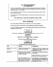
Grounding Instructions
f '''' "" m
WARNING
• IIIIII IIII
I[V;,PROPERGROUNDING CAN RESULT INA
R!SK OF ELECTRICAL SHOCK, IN THE
-VENT OF A SHORT CIRCUIT, GROUNDING
R-:)UCES THE RISK OF SHOCK BY PRO-
VIDING AN 5SCAPE WIRE FOR THE ELEC-
TRIC CURRENT, THIS COMPRESSOR MUST
BE PROPERLY GROUNDED. READ THE
FOLLOWING iNSTRUCTIONS.
1. The compressor is equipped with a cord having a
grounding wire with an appropriate grounding plug.
The plug must be used with an outlet that has been
properly installed and grounded in accordance with
all local codes and ordinances. The outlet must have
the same configuration as theplug, DO NOT USE AN
ADAPTER.
2, If repair or replacement of the cord or plug is ever
necessary, do not connect the grounding wire to
either flat blade terminal. (The grounding wire has
insulation with an outer surface that is green- with or
without yellow stripes.)
3. Do not modify the plug that has been provided, If it
does not fit the available outlet, the correct outlet
should be installed by a qualified electrician.
If these grounding instructions are not completely
understood, or if in doubt as to whether the compressor
is propedy grounded, have the installation checked by a
qualified electrician or serviceman.
Start-Up Procedures
All units are shipped without oil. Serious
damage may result if the following break-in
instructions are not closely followed. This
operation has to be completed only once
when first putting the unit in service,
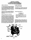
PlaCeunit on a level surface. Remove oilfillplug (51) and
slowly add a special compressor oil such as Sears
9H6426 or SAE 20=20W SF motor oil until it is even with
the topof the oil fillhole. When filling the crankcase, the
oil flows intoitvery slowly.If theoil is added too quickly,it
will overflow and appear to be full. (It takes 16 fluid
ounces of oil ot fill the crankcase.) Under winter-type
conditions use SAE 10W oil. Multi-viscosity oil (10W30)
may be used but will result in carbon deposits on critical
components and reduce performance and compressor
life. Replace oil fill plug (51). Plug the compressor into
the correct power source. Start the compressor by
switching the ON-AUTO/OFF switch (19) to the ON-
AUTO position. Turn the regulator knob (23) clockwise
fully to permit air to escape and prevent air pressure
bui!dup in the air tank. RUN THE COMPRESSOR 30
MINUTES IN THIS MANNER TO LUBRICATE PIS-
TONS AND BEARINGS. Shut off air with regulator knob
(turn counterclockwise) and let the unit pump up to cut
off pressure. Turn the switch to "OFF" and check the oil
level; add oil if necessary, Turn switch to _ON" and the
unit isready for use. Connect the air hose tothe air outlet
connection (27) located on the front of the console.
Refer to Figure 1.
OPERATION
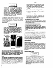
Control Console
The control console (33) is located on the front of the
unit. The air pressuro coming from the air tank is con-
trolled by the regulator knob (23). Turn the regulator knob
clec_ise toincrease pressure and countemlockwise to
decrease pressure. To avoid minor readjustment after
making a change in pressure setting, always approach
the desired pressure from a lower pressure. When
reducing from a higher to a lower setting, first reduce to
some pressure less than that desired, then bring up to
the desired pressure. Depending on the air flow require-
ments of each particular accessory, the outlet regulated
air pressure mighthave tobe adjusted under flow condi-
tions, Also on the console is the ON-AUTO/OFF switch,
air outlet, safety valve and two pressure gauges. One
gauge shows the air tank pressure and the other the
outlet regulated pressure. Refer to Figure 2.