Assembly
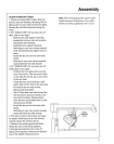
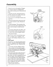
7, Rotate the saw to the negative 45 degree
l_'cx,_c!position. Remove and discmd ttle
oflmr lmndle retaining screw, Discard tile old
handle,
8. Using the two #1(1 x 3/4 flat head screws
provided, altach the new h;mdle in tile same
way as the old one was renloved,
9o Return lhe saw to the blade vertical, cross-
cut position.
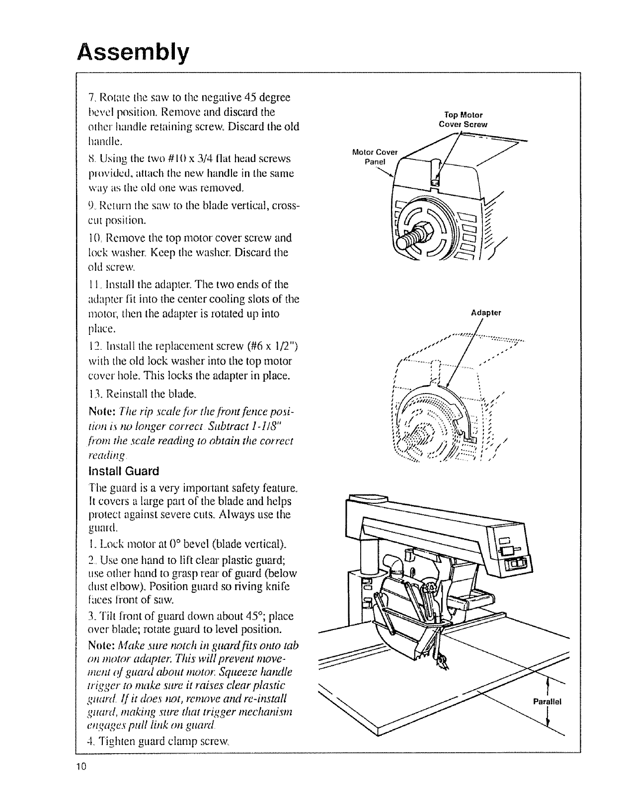
10, Remove the top motor cover screw and
lock washer: Keep the washer, Discard the
old screw,
11, Install the adapter: Tile two ends of' tile
adapter fh into tile center cooling slots of the
motor; then the adapter is rotated tip into
phlce.
12. Install the replacement screw (#6 x 1/2")
with the old lock washer into the top motor
cover hole. This locks tile adapter in place.
13, Reinstall the blade°
Note: Tim rip scale fi_r the fi'ont fence posi-
tirol i._no longer cotvect Subtract 1-1/8"
fiom the ._'cale reading to obtain the correct
reading,
Install Guard
The guard is a very important safety feature_
It covers a large part of tile blade and helps
protect against severe cuts, Always use the
gumd.
1. Lock motor at 0 ° bevel (blade vertical).
2, Use one hand to lift cleaa" plastic guard;
use od_er hand to grasp fear of guard (below
dust elbow). Position guard so riving knife
fuces front of saw.
3oTilt fiont of guard down about 45°; place
over' blade; rotate guard to level position,
Nole: Make .uae notch in guardfits onto tab
on motor adapter. This wUl prevent move-
merit o/guard about motor Squeeze handle
u'igger to make sure it raises clear plas-tic
guard l[ it &_es ,tot, remove and re-install
gtuud, makiltg sure that trigger mechanism
engages pull link on guard,
-'LTighten guard clamp screw,
Motor Cover
Panel
Top Motor
Cover Screw
Parallel
10


