


Senco
®
Gasoline Air Compressor Manual 2000 9
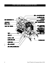
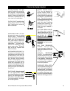
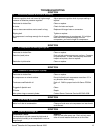
OIL SIGHT GLASS: The sight
glass will register the amount of
oil in the pump. Oil level should
be checked on a daily basis to
ensure it does not exceed the
maximum or fall below the mini-
mum level on the sight glass.
OIL FILL PLUG: To add oil to the
pump, simply remove the oil fill
plug. Replace when correct oil
level is achieved.
AIR INTAKE FILTER: This filter
is designed to clean air coming
into the pump. To ensure the
pump continually receives a
clean, cool, dry air supply this
filter must always be clean and
ventilation opening free from
obstructions. The filter can be
removed for cleaning by using
warm, soapy water. Rinse the
filter and air dry. Replace filter
when necessary.
AIR COMPRESSOR PUMP: To
compress air, the pistons move
up and down in the cylinders. On
the downstroke, air is drawn in
through the air intake valves while
the exhaust valves remain
closed. On the upstroke, air is
compressed, the intake valves
close and compressed air is
forced out through the exhaust
valves, into the discharge line,
through the pilot valve and into
the air tank.
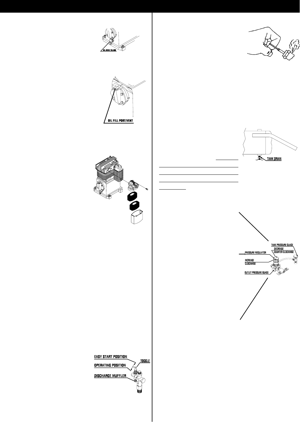
PILOT VALVE: When the toggle
is in the upright position, all air
from the air compressor is vented
through the discharge muffler.
This gives an easy start feature.
For normal operation, the toggle
is in the 90° position.
SAFETY RELIEF VALVE:
This valve is designed to
prevent system failures by
relieving pressure from the
system when the compressed
air reaches a predetermined
level. The valve is preset by
the manufacturer and must not
be modified in any way. To
verify the valve is working
properly, pull on the ring. Air
pressure should escape.
When the ring is released, it
will reseat.
AIR TANK DRAIN VALVE:
The drain valve is used to
remove moisture from the air
tank(s) after the air compres-
sor is shut off. NEVER
attempt to open the drain
valve when more than 10
PSI of air pressure is in the
air tank! To open the drain
valve, turn the knob counter-
clockwise.
AIR TANK PRESSURE
GAUGE: The air tank
pressure gauge indicates the
reserve air pressure in the air
tank (s).
OUTLET PRESSURE
GAUGE: The outlet pressure
gauge indicates the air pres-
sure available at the outlet side
of the regulator. This pressure
is controlled by the regulator
and is always less or equal to
the air tank pressure.
PRESSURE REGULATOR:
The air pressure coming from
the air tank is controlled by the
regulator knob. Turn the pres-
sure regulation knob clockwise
to increase discharge pres-
sure, and counterclockwise to
decrease discharge pressure.
0MAC0065 0MAC0055-DUB
0MAC017-DUB 0MAC019-DUB PRESRING.TIF
0MAC020-DUB
PC2015 FEATURES REVIEW
0MAC0056-DUB