


2
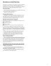
This manual contains information for the proper assembly,
operation and care of your SP415 sprayer. Carefully read and
follow the instructions contained in this manual before operat-
ing your sprayer.
Specifications
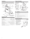
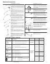
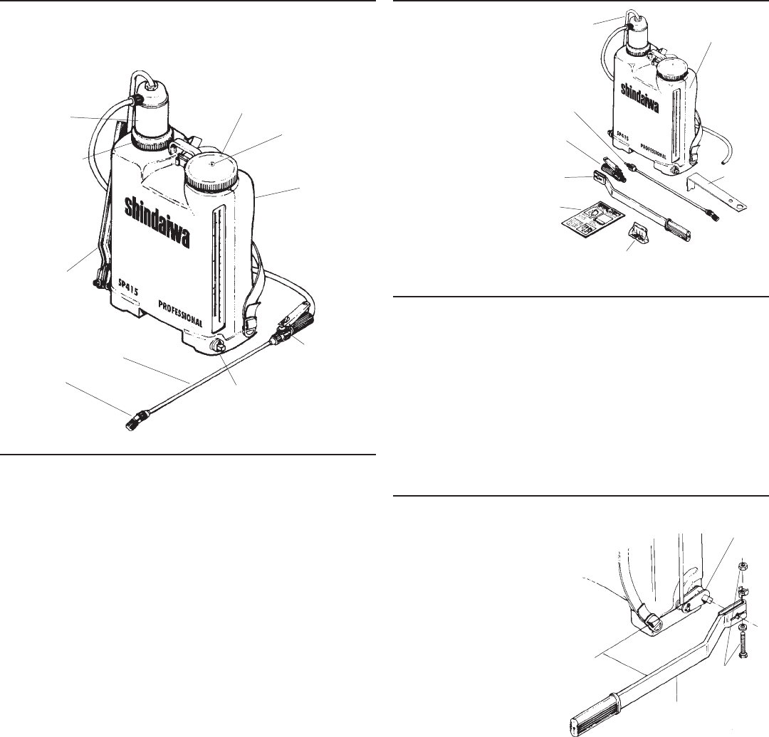
Unpack the following
items shipped in
your sprayer box:
■ Wand
■ Pump Lever and
Connecting Rod
■ Tank Assembly
■ Small Parts Kit
■ From inside the
sprayer tank,
remove the
plastic bag from
the tank strainer.
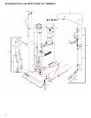
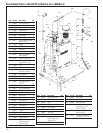
Pump
Chamber
Vent
Diaphragm
Cap
Lever
Tank
Nozzle
Wand
Trigger Valve
Trigger
Valve
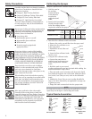
Small Parts Kit
(Includes the following components)
Manual
Pump
Lever
Connecting
Rod
Wand
Tank
THE SERIAL NUMBER IS
LOCATED ON THE BOTTOM
OF THE TANK.
Packing Ring
Nut
Net Weight ..................................................... 10.5 pounds (4.8 kg)
Tank Capacity .......................................... 4 U.S. gallons (15 liters)
Tank Material ..............................................Polyethylene (Plastic)
Fill Opening Diameter .................................. 4.5 inches (114 mm)
Pump .............................................................................. Piston Type
Pump Material ......................... Polypropylene with UV Protector
Operating Pressure ....................... 15-90 psi (1.05-6.3 kg/sq. cm)
Wand Assembly Length .......................... 27.5 inches (698.5 mm)
Hose Length............................................. 69.75 inches (1771 mm)
Nozzle Installed ............................................ Red Adjustable Cone
Specifications subject to change without notice.
Introduction
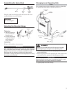
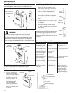
1. Align the pump lever with
the pump shaft linkage
as shown. (chamber side).
2.
Install the pump lever on
the pump shaft and secure
with the lever bolt
assembly.
3. Tighten the lever bolt until
the lever clamp grips the
pump shaft securely.
Install the Pump Lever
Pump Lever
Shaft
Bolt
Assembly
Prepare to Assemble
Piston
Wrench
Parallel
Pump Shaft
Linkage
568970 Trigger Valve Needle Assembly....................................................... 1
105254 Trigger Valve Cap............................................................................... 1
908905 Diaphragm ........................................................................................... 2
214585 45 x 12 Piston Cup .............................................................................. 1
210088 No. 12 Disc .......................................................................................... 1
210195 Swirl Core ............................................................................................ 1
457416 Kematal DEF-06 Deflector Flat Fan Nozzle (Grey)....................... 1
437885 Kematal 110-LD-03 Low Drift Flat Fan Nozzle (Blue)................... 1
217174 Stainless Steel Cone Nozzle ............................................................. 1
229724 Nozzle Cap........................................................................................... 1
P/N Description Qty.