


-9-
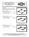
D2057A, D2058A, D2260A Mobile Base Instructions
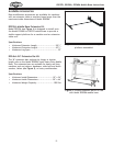
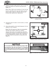
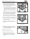
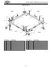
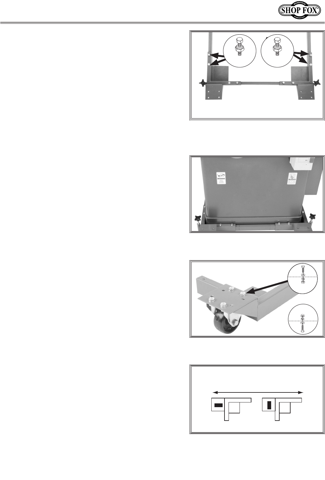
Figure 21. Corner bracket-rail assembly
placed under front of machine.
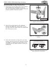
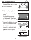
7. Slide the other ends of the rails into the corner
brackets from Step 6. Secure each end of the rails
to the corner brackets with (2) M8-1.25 x 25 hex bolt
and 8mm lock nut assemblies (see Figure 20).
8. Tighten lock nuts against the rails.
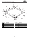
Figure 20. Rails fastened to brackets.
(Machine removed from assembly for
clarity.)
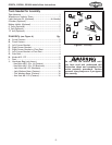
9. While an assistant lifts one side of the machine up,
slide the front rail-bracket assembly from Step 7
under the machine, as shown in Figure 21.
Note: It may be necessary to re-adjust the position
of the rails once the machine is actually on the base
assembly.
Side rails may be cut down to accommodate
machines with smaller footprints. However,
reducing the length of the mobile base decreases
stability and increases the likelihood of tipping
tall or top heavy machines. Base plates should be
constructed for tall or top heavy machines (see Page
12).
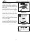
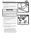
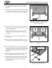
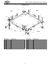
10. Mount each of the two fixed casters to the remaining
corner brackets with the eight hole pattern using (4)
M8-1.25 x 16 hex bolts, 8mm flat washers, 8mm lock
washers and M8-1.25 hex nuts, as shown in Figure
22.
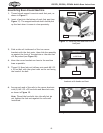
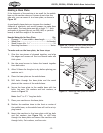
Orient the fixed casters so they point in the same
direction that your machine will typically be moved
(see Figure 23). Mounting the fixed casters in the
wrong direction will make it difficult to move your
mobile base.
Note: Patience is required when installing the
fasteners inside the bottom of the fixed casters due
to space constraints.
Figure 23. Mounting casters based upon
typical direction of movement.
Typical Direction of Movement
(TOP VIEW OF CASTER)
CORRECT INCORRECT
Figure 22. Mounting fixed casters to eight
hole pattern corner brackets.
x 2 x 2
or
x 4
x 4