


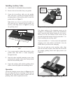

Installing Auxiliary Table
1. DISCONNECT GRINDER FROM POWER!
2. Remove the tool rest table from your grinder.
3. Center the jig auxiliary table over the grinder
table, then use a scratch awl through the three
mounting holes of the auxiliary table to mark the
grinder table (see Figure 3).
Note: Make sure that you position the tables so
that when the jig is mounted on the grinder, the
auxiliary table edge shown in Figure 3 is facing
the grinding wheel.
4. Use a center punch to indent these marks on the
grinder table, then drill
7
⁄32" holes completely
through the table.
5. Insert the three included mounting screws from
underneath the grinder table, then loosely thread
them into the auxiliary table.
6. Square the auxiliary table with the grinding wheel
surface, then fully tighten the mounting screws.
Operation
Loosen the clamping screws shown in Figure 4, slide
the tool under the top bar and align its left side up
against the 90° stop pins to make it square with the
grinding wheel, then re-tighten the screws.
Figure 4. Clamping screws, washers, and stop pins.
90° Stop
Pins
Clamping
Screws &
Washers
The plastic washers of the clamping screws can be
arranged to accommodate various tool thicknesses
and to provide good thread bearing for the screws.
However, be sure the bottom of the screws do not
protrude beyond the bottom of the jig more than
1
⁄8" to
avoid scratching the auxiliary table.
If your tool width is 1
1
⁄8" or less, remove the right-hand
clamping screw and washers and thread it into the
middle hole to provide secure clamping.
Place the tool and jig on the auxiliary table, align
and lock the table in place, then slide the tool across
the rotating grinding wheel with light pressure (see
Figure 5).
Figure 5. Plane iron clamped in the jig.
Figure 3. The mounting holes of the jig auxiliary
table.
Mounting Holes
Auxilary Table Edge Faces Grinder