


-12-
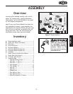
ASSE MBLYASSE MBLY
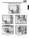
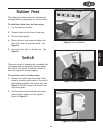
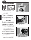
Figure 11. Suggested lifting procedure.
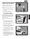
Figure 12. Shipping brace.
To mount the Planer/Moulder head, do these
steps:
1. Lay two 2x4’s on the table and lower the
cutterhead to clamp the 2x4’s in place as
shown in Figure 11.
2. Using mechanical lifting equipment or
helpers, lift with the 2x4’s and set the
planer/moulder head on the stand.
3. Secure the planer/moulder head to the
stand with four
5
⁄16"-18 x 1
1
⁄2" hex bolts, flat
washers, lock washers, and hex nuts.
Drive Belt
The weight of the motor holds the drive belt
tight. The drive belt then transfers power from
the motor to the cutterhead.
To install the drive belt, do these steps:
1. Remove the shipping brace shown in Figure
12. Replace the motor mounting bolt after
removing the brace.
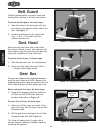
2. Feed the belt through the slot in the base
and over the cutterhead pulley with the
arrows on the belt pointing the direction
shown by the arrow in Figure 13.
3. Have an assistant swing the motor up and
support it until the belt is in place.
4. Slide the drive belt around the motor pulley
as shown in Figure 13 and lower the motor
to tension the drive belt.
6. If the drive belt is not vertical, loosen the
setscrew in the upper pulley and slide the
pulley in or out until the belt is vertical.
Figure 13. Installing the drive belt
(Belt cover removed for clarity).
Planer/Moulder Head
Shipping Brace
USE helpers or power
lifting equipment to lift
this Planer/Moulder.
Otherwise, serious per-
sonal injury may occur.