


-28-
W1747 20" Planer
SERVICE
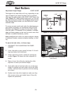
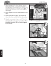
6. Position the knife gauge over the knife as shown in
Figure 17 and loosen the gib bolts until the knife is
completely loose.
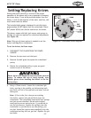
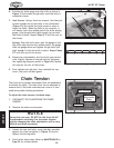
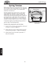
7. Jack Screws—Using a 3mm hex wrench, find the jack
screws through the access holes in the cutterhead
(Figure 19) and rotate the jack screws to raise or
lower the knife. When the knife is set correctly, it
will barely touch the middle pad of the knife setting
gauge. Snug the gib bolts tight enough to just hold
the knife in place. Repeat Steps 5-7 with the rest of
the knives.
Springs—Push the knife down with the gauge so that
the knife edge touches the middle pad of the gauge.
Hold the gauge down and tighten the gib bolts just
tight enough to hold the knife in place. Repeat
Steps
5-7 with the rest of the knives.
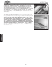
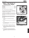
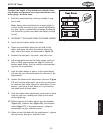
8. Rotate the cutterhead to the first knife you started
with. Slightly tighten all the gib bolts by following
the tightening sequence shown in
Figure 20. Repeat
this step on the rest of the knives.
9. Final tighten each gib bolt, then reinstall the top
cover, dust port and bolt guard.
Figure 19. Jack screw access hole.
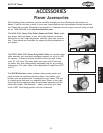
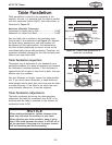
Chain Tension
The chain drive transfers movement from the handwheel
to elevate the table. The chain drive can be adjusted to
remove slack if the chain stretches over time or is loos
-
ened during table leveling procedures.
To adjust the chain tension, do these steps:
1. DISCONNECT THE PLANER FROM THE POWER
SOURCE!
2. Remove the motor access panel.
NOTICE
During the next step, DO NOT let the chain fall off
the sprockets—returning it to its proper location
without changing the table adjustments will be very
difficult and time consuming.
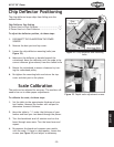
3. Loosen the two lock bolts, move the idler sprocket
against the chain to tighten it (
Figure 21) and re-
tighten the locking bolts.
4. Check chain lubrication. Refer to MAINTENANCE on
Page 23 for further details.
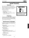
Figure 21. Underside of table.
Lock Bolts
Idler Sprocket
Figure 20. Gib bolt tigthening sequence.
1
2
3
4
5 6
Table Height
Adjustment
Chain
OFF