


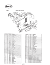
Dismantling
&
Assembly
Disconnect
loo)
from
air
supply
Lift
cover(44).
press
down
stoppef(28)
10
reduce tension
on
the
abrasive belt and
push
on idle pulley(40)
10
remove
belt.
Remove capscrew(38)
and
washer(37)
to
remove
shoe(32). Take out
2 off
scfews(38)
and
2
off
washers(37)
to removs tingaplate(39).
Take
out
ide
shaft
screw(42)
to
release ide pulley assembly.
"The
ide
pulley
assembly
may
be
dismantled
by tapping out
the
bearings(41)
from idle
pulley(40)
releasing cdlar(43).
Drive
out pin(45) to remove
whee)
cover 1444). Take out
2
off
capscfews(33)
to
release
cover
latch(&).
PuU
out
~(27).
Belt
alignment
countersunk
screw
may
be
removed
from
tenson
arm(35)
if
a
replacement
is
required.
Drive
out
stop
pin(36)
and
pull
out tension
m(36)
and spring(34).
Drive
out
roll pin(=)
to
release stopper(28) and stopper spring(29).
Insert
rod
in
hole
of drive putley(22) to prevent rotation
and
unscrew
nut(24)
with
washer(23). Take off
drive
pullev(22).
Note
how
drive
puIlev(22) locates on pin(19)
in
rotor(
17).
Unscrew
capscrew(31) to remove
wheel
cover(26).
Unscrew air
inlet(11) from motor
housing(1)
aid
take
off
detector(l0).
Drii
out
pin(9)
to
remove
lever(€! Unscrew
mfve
body(7) and take
out
Orinas(6)
end
(5).
valve
aem(4)
with
O-ring@)
and
-2).
Unscrew motor
nut(12)
from
motor
houaing(1)
with
Mng(13).
Tap
carefully.
so as
not
to
damage
the
head. rota(l7) to
remove
the
motor
assemUy
Irm
rnota housing(1). Rn(19)
can
be
taken
cat
of
rotod17).
Note
how
the
pin(25)
in
cv(ndarf16)
locates
the
motor
assembly
in
tho
groove
in
the
motor
housing(1) and that
the
pin(25)
is
at
the
rear
end
plate(l5)
end.
Hold
motor
assembly and again
tap
the
threaded
end
of
the
rotd17) to
drive
it
through
the
front
end
p(ate(15) and bearing(14) assembly. Eearina(14)
may
be
lapped
out
of
front
end
plalfl5).
Take
off
cylinder(l6) and 4 off rota blactes(18).
Support
the
rear end plate(l5) in a piece of tube
with
a bore diameter
as
dose
as
possible
to
the
mahum
diameter of
the
rotor and
tap
the
non
Dreaded
end
of
the
rotor(17) through
the
rear
end
plate
assembly.
Tap
out
bearing(21)
frm
front
plate(20).
Reassembly
Qean
all
parts
and examine
for
wear.
particularly O-rings.
bearings
and
rotor
blades.
Use
only
dsttibutor
or manufacturer supplied
spare
parts.
Pack
all
bearings
with
a
general purpose grease and
reassemble
h
Ihe
reverse order. Reft
belt
and
adfist
alignment using
screvirf47).
Notes
1
Declaration
of
Conformity
Sioux
Tools
Inc.
290
1
Floyd
Boulevard,
P.
0.
Box
507,
Sioux
City,
Iowa
5
1
102,
U.S.A
declare
under
our
sole
responsibility
that
the
product
Model
5562
20rnrn
Belt
Sander,
Serial
Number
10
uKch
iMs
declaration
relates
is
n
conformity
Viih
the
folwhg
standard(s)
or
oh
norm&
documantfs)
EM792
(Draft);
EN292
Parts
1
&
2,
IS0
8662
Parts
1
&
8,
Pneurop
PN8WC1
fciio~ng
(ha
prowsions
or
89/392/EEC
as
amended
by
9
1/368/EEC
&
93/44/EEC
Directives
Paoak4
Primed
in
Japan
12/96