


-11-
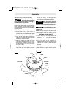
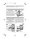
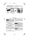
DEPTH ADJUSTMENT WITH PLUNGE
BASE PLUNGING ACTION
The plunge feature simplifies depth
adjustments and will allow the cutting bit to
easily and accurately enter the workpiece.
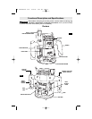
To lower, loosen lock lever (Fig. 11), and
apply downward pressure until you reach
desired depth, and tighten lock lever. Loosen
lever and release pressure and the router will
automatically retract the bit from the
workpiece. It is advisable to retract the bit
whenever it is not engaged in workpiece.
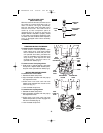
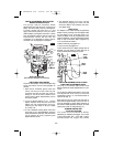
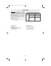
DEPTH ROD AND TURRET
The Auto-Zero depth rod and the depth stop
turret are used to control cutting depth as
follows;
1. With the bit installed, gently lower the
motor until the tip of the router bit just
contacts the level surface the router is
sitting on. This is the “zero” position, from
which further depth adjustments can be
accurately made.
2. To set a desired depth of cut. Loosen
depth indicator knob and the auto-zero
depth rod will automatically zero-out,
meaning you are ready to set your depth
of cut (Fig. 12).
3. To set a desired cutting depth, lower the
auto-zero to your required depth using the
scale attached to the base, and secure the
rod in position by firmly tightening the
depth indicator knob.
4. The desired depth of cut may now be
achieved by plunging the router until the
auto-zero depth rod contacts the auto-
zero depth stop.
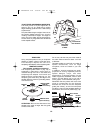
DEEP CUTS
For deeper cuts, make several progressively
deeper cuts by starting with the highest step
on the depth turret, and after each cut,
rotate the depth turret to progressively lower
steps as desired, until the final depth (lowest
step or flat) is reached. Steps progress by
1/4" increments as follows.
• Both turrets fully engaged 1/2".
• Top turret fully engaged 1/4".
To be certain that your depth settings are as
desired, you may want to make test cuts in
scrap material before beginning work.
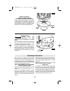
DEPTH ADJUSTMENT WITH PLUNGE
BASE FINE ADJUSTMENT KNOB
The pop up fine depth adjustment knob
allows precise bit height adjustments on your
router.
To use the fine adjustment feature, pull up the
fine adjustment knob and turn the knob
clockwise to lower, or counterclockwise to
raise the bit (Fig. 4).
(Note that one full turn of the knob will raise or
lower the bit approximately 1/16"of an inch. It
may be necessary to exert slight pressure on
the router handle opposite the knob, to avoid
cocking the motor on the posts (Fig. 4).
TRIGGER SWITCH AND
“LOCK-ON” BUTTON
Your router can be turned ON or OFF by
squeezing or releasing the trigger. Your router
is also equipped with “Lock-ON” button
located above the trigger that allows
FIG. 11
DUST PORT ADAPTER
(Not included, available as accessory)
DEPTH
STOP
TURRET
DEPTH
SCALE
DEPTH
GAUGE
KNOB
FIG. 12
TO LOOSEN
BM 1619X00324 3-04 3/16/04 2:13 PM Page 11