


-9-
"<1>-@5:3:?@>A/@5;:?
($%#"!&$"
&$$%)&
Your tool is equipped with a variable speed
trigger switch. The tool speed can be
controlled from the minimum to the maximum
nameplate RPM by the pressure you apply to
the trigger. Apply more pressure to increase
the speed and release pressure to decrease
speed. This accurate speed control enables
you to drill without center punching. It also
permits you to use as a power screwdriver.
Bits are available for driving screws as well as
running bolts and nuts.
"$)$$($%!($
&$$"
After tool use, lock trigger in
“OFF” position to help prevent
accidental starts and accidental discharge.
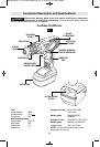
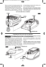
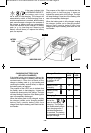
Your tool is equipped with a forward/
reversing lever and trigger lock located above
the trigger (Fig. 1). This lever was designed for
changing rotation of the bit, and for locking the
trigger in an “OFF” position.
For forward rotation, (with chuck pointed away
from you) move the lever to the far left.
For reverse rotation move the lever to the far
right. To activate trigger lock move lever to the
center off position.
;:;@/4-:3105>1/@5;:;2
>;@-@5;:A:@58@41@;;8/;91?
@;-/;9<81@1?@;<Shifting during rotation of
the chuck can cause damage to the tool.
'%&'&
Your tool features 16 clutch settings. Output
torque will increase as the clutch ring, is
rotated from 1 to 15. The drill “ ” position
will lock up the clutch to permit drilling and
driving heavyduty work, and also enables bits
to be changed quickly and easily in the keyless
chuck.
$
When the trigger switch is released it activates
the brake to stop the chuck quickly.
This is especially useful in the repetitive driving
and removal of screws.
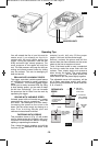
!%$&!&%
Move reverse switch lever to the center “OFF”
position. Remove battery pack and rotate the
clutch ring to the drill bit symbol
“ ”. Rotate the chuck sleeve counter-
clockwise viewing from chuck end, and open
chuck to approximate drill bit diameter. Insert
a clean bit up to the drill bit flutes for small bits,
or as far as it will go for large bits. Close chuck
by rotating the chuck sleeve clockwise and
securely tighten by hand (Fig. 2).
;:;@A?1@41<;C1>;2@41
0>588C45813>-?<5:3/4A/7
@;8;;?1:;>@534@1:.5@ Friction burn or hand
injury is possible if attempting to grasp the
spinning chuck.
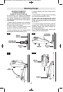
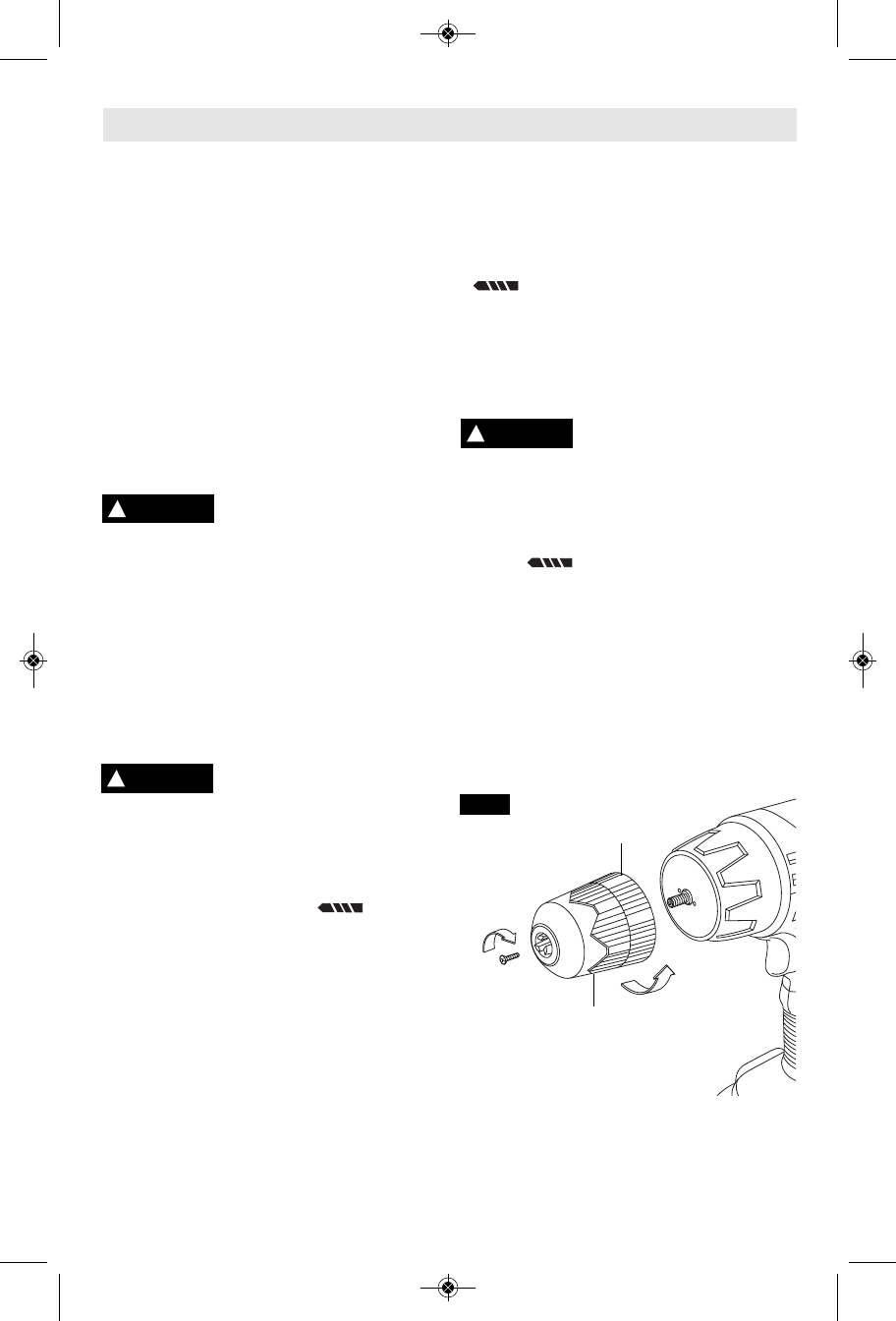
$ "(!'
Rotate the clutch ring to the drill bit
symbol “ ”. Open the chuck all the way,
remove left-hand thread screw inside chuck by
turning it clockwise. Insert the short arm of a
3/8" hex key wrench and close jaws on flats of
wrench. Strike long arm of wrench sharply
counterclockwise, remove wrench and
unthread chuck from spindle (Fig. 2).
!%&!'
Always keep the spindle threads, the threads
of the chuck and securing screw free of
debris. To install a chuck, reverse “re moving
the chuck” procedure.
!
CAUTION
!
WARNING
!
WARNING
clockwise
Counter
clockwise
CHUCK
SLEEVE
CHUCK
COLLAR
FIG. 2
SM 1619X04717 04-10:SM 1619X04717 04-10 4/22/10 9:57 AM Page 9