


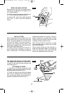
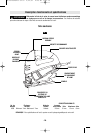
Attaching the Blade
To prevent personal injury,
a
lways disconnect plug from
power source before assembling parts, making
adjustments, or changing blades.
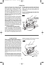
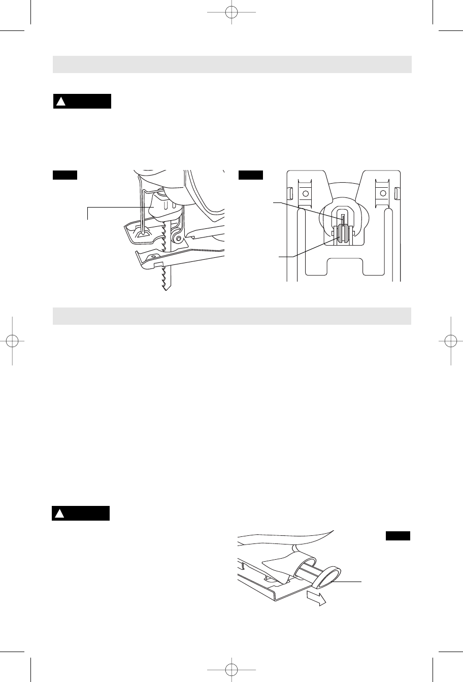
1. Insert the saw blade (teeth in cutting
direction) until it latches in the plunger
(Fig. 2).
When inserting the saw blade, the back of
the blade must rest in the groove of the
guide roller (Fig. 3).
2. To remove blade, lift tool-less blade change
cover up with index finger and thumb and
remove blade.
For use with both T or U shank jigsaw blades.
-7-
Assembly
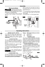
TRIGGER "ON-OFF" SWITCH
TO TURN THE TOOL "ON" squeeze the
trigger switch. TO TURN THE TOOL "OFF",
release the trigger switch, which is spring
loaded and will return to the "OFF" position
automatically.
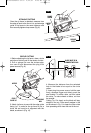
"LOCK-ON" BUTTON
The "Lock-ON" button, located in the handle of
your tool allows for continuous operation at
maximum SPM without holding the trigger
(Fig. 1).
TO LOCK TRIGGER "ON": squeeze trigger,
depress button and release trigger.
TO UNLOCK THE TRIGGER: squeeze trigger
and release it without depressing the "Lock-
ON" button.
If the “Lock-ON” button is
continuously being depressed,
the trigger can not be released.
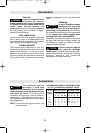
VARIABLE SPEED DIAL
Your tool is equipped with a variable speed
dial. The blade stroke rate may be adjusted
during cutting operation by presetting the dial
on or between any one of the six numbers.
Setting SPM rating (strokes per minute)
1-2 Low stroke
3-4 Medium stroke
5-6 High stroke
PLUNGER SPEED
The stroke rate may be adjusted as described
earlier under “Variable Speed Dial”. The best
results for a particular application is determined
by experience, though as a general rule, slower
speeds are for denser materials and faster
speeds are for soft materials.
BLADE STORAGE COMPARTMENT
Your tool is equipped with a blade storage
compartment on the backside of your saw
(Fig. 3). To remove, pull compartment in
direction of arrow.
Always make sure the blade storage
compartment is securely in housing to prevent
blades from falling out.
!
WARNING
!
WARNING
Operating Instructions
FIG. 2
FIG. 3
TOOL-LESS
BLADE CHANGE
COVER
ROLLER
GUIDE
BLADE
BLADE
STORAGE
COMPARTMENT
FIG. 3
SM 2610948279 02-07 2/22/07 4:28 PM Page 7