


-10-
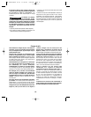
blade well clear of the work. Start the motor,
and then very gradually lower the blade.
When it touches, continue pressing down on
the toe of the saw foot slowly pivoting the
saw like a hinge until the blade cuts through
and the foot rests flat on the work. Then saw
ahead on the line of cut line. We do not
recommend plunge cutting with a scroll blade
(Fig. 5).
To make sharp corners, cut up to the corner,
then back up slightly before rounding the
corner. After the opening is complete, go
back to each corner and cut it from the
opposite direction to square it off. Do not try
to plunge cut into hard materials such as
steel.
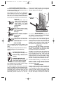
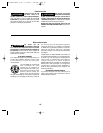
CIRCLE AND PARALLEL CUTTING GUIDE
This accessory is available at an extra cost. It
is used for fast and accurate straight and
circle cutting (Fig. 6).
ATTACHING GUIDE
1. Insert bar of guide through lock knob
clamp, then through the slots provided in
foot, from either side of foot with the edge
guide facing down (Fig. 6).
2. Hook lock knob clamp onto edge of
footplate, adjust fence to desired width, and
securely tighten lock knob clamp.
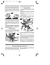
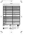
CIRCLE CUTTING
1. Before attaching the guide, draw a circle
and predrill a 13/64” center hole in
workpiece.
2. Drill or plunge cut near the circles edge,
turn saw off and move the switch lock to the
lock position.
3. Attach guide to saw with edge guide facing
UP as shown (Fig. 7).
4. Remove guide pin from end of guide,
push pin through hole provided in guide,
then into center hole of workpiece.
5. Measure the distance from the selected
hole to the blade to be equal to the circle
radius.
6. Move switch lock to the unlock position,
hold the saw firmly, squeeze trigger and
slowly push the saw forward. To make a hole,
cut from inside the circle; To make wheels or
discs, cut from the outside.
Cutting Tip: Cut slowly so the blade will stay
straight in the cut. Place small wedges in the
cut as shown in Fig. 7, to keep the inner circle
from spreading when near the end of the cut.
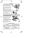
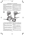
RELEASING AND INSERTING BATTERY PACK
Release battery pack from tool by pressing
on both sides of the battery release tabs and
pull downwards. Before inserting battery
pack, remove protective cap from battery
pack. To insert battery, align battery and
slide battery pack into tool until it locks into
position. Do not force.
FIG. 5
1
2
FIG. 6
LOCK
KNOB
CLAMP
GUIDE
PIN
FIG. 7
GUIDE
PIN
HOLE
GUIDE
PIN
BAR
EDGE GUIDE UP
WEDGE
EDGE GUIDE DOWN
BM 2610916876 11-03 11/19/03 3:02 PM Page 10