-8-
Assembly
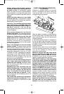
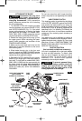
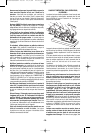
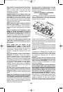
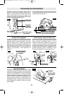
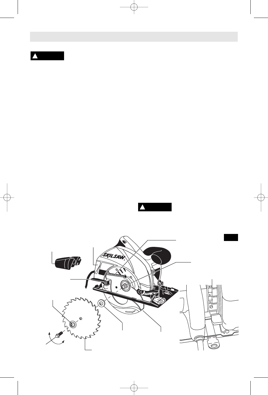
ATTACHING THE BLADE
Disconnect the plug from
the power source before
making any assembly, adjustments or
changing accessories
. Such preventive
safety measures reduce the risk of starting
the tool accidentally.
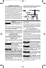
1. Turn BLADE STUD with wrench provided
counter-clockwise and remove BLADE STUD
and OUTER WASHER (Fig. 2). If the shaft
moves while attempting to loosen the blade
stud press the lock button. On models 5400,
5450, 5500, 5600, & 5650 strike the wrench
counter-clockwise to jar BLADE STUD loose.
2. Retract the lower guard all the way up into
the upper guard. While retracting the lower
guard, check operation and condition of the
LOWER GUARD SPRING.
3. Make sure the saw teeth and arrow on the
blade point in the same direction as the arrow
on the lower guard.
4. Slide blade through slot in the foot and
mount it against the INNER WASHER on the
shaft. Be sure the large diameter of the OUTER
washer lays flush against the blade.
5. Reinstall OUTER WASHER and tighten
BLADE STUD finger tight. Press lock button to
lock shaft. To lock shaft on models 5400, 5450,
5500, 5600, & 5650 hold the saw securely by
the upper guard with blade teeth imbedded in
scrap wood. For all models TIGHTEN BLADE
STUD 1/8 TURN (45°) WITH THE WRENCH
PROVIDED.
Do not use wrenches with longer handles,
since it may lead to over tightening of the blade
stud.
VARI-TORQUE CLUTCH
This clutching action is provided by the friction
of the OUTER WASHER against the BLADE
and permits the blade shaft to turn when the
blade encounters excessive resistance. When
the BLADE STUD is properly tightened (as
described in No. 5 of Attaching The Blade), the
blade will slip when it encounters excessive
resistance, thus reducing saw’s tendency to
KICKBACK.
One setting may not be sufficient for cutting all
materials. If excessive blade slippage occurs,
tighten the blade stud a fraction of a turn more
(less than 1/8 turn). OVERTIGHTENING THE
BLADE STUD NULLIFIES THE EFFECTIVE-
NESS OF THE CLUTCH.
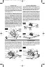
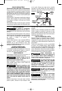
DUST EXTRACTION
(Not included, available as accessory)
Your tool is equipped with a dust port adapter
for dust and chip extraction. To attach, push
tabs on end of adapter into dust port until it
snaps into place. To use this feature, attach
standard 1-1/4" vacuum hose (optional
accessory) to the dust port adapter.
To prevent personal injury,
always position dust port
adapter and vacuum hose so that it does
not interfere with the lower guard, or the
cutting operation at all settings.
!
WARNING
!
WARNING
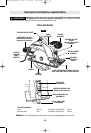
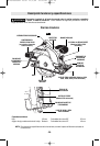
FIG. 2
Tighten
Loosen
BLADE
STUD
LOCK BUTTON
(Model 5700 only)
LOWER GUARD
SPRING
OUTER WASHER
Large Diameter
Faces Blade
INNER WASHER
Large Diameter
Faces Blade
BLADE
LOWER
GUARD
BLADE SHAFT
DUST
PORT
DUST PORT ADAPTER
(Not included,
available as accessory)
LOWER GUARD
LIFT LEVER
SM 2610925541 10-04 11/1/04 12:23 PM Page 8