


Operating Instructions
VARIABLE SPEED CONTROLLED
TRIGGER SWITCH
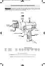
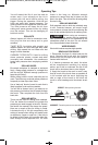
Your tool is equipped with a variable speed
trigger switch. The tool can be turned "ON" or
"OFF" by squeezing or releasing the trigger.
The speed can be adjusted from the minimum
to maximum nameplate RPM by the pressure
you apply to the trigger. Apply more pressure
to increase the speed and release pressure to
decrease speed (Fig. 1).
REVERSING SWITCH LEVER
The reversing switch lever is located above the
trigger switch and is used to reverse rotation of
the bit. The reversing switch should only be
activated when the motor is “OFF” and when bit
is at a com plete standstill (Fig. 1).
To use tool in “Forward” rotation move lever to
left side of tool, to “Reverse” the rotation of the
bit move the lever to the right side of the tool.
Do not change direction of
rotation until the tool comes to
a complete stop. Shifting during rotation of the
chuck can cause damage to the tool.
DRILL LEVEL
Your tool is equipped with drill level located on
top of the housing that will allow you to
accurately enter the workpiece in a horizontal
position (Fig. 1).
USING THE LEVEL: Place drill bit where hole
is to be drilled, position drill so the bubble in the
level is centered between the lines, then start
drilling the hole, once the bit has entered the
workpiece check from time to time to be sure
the bit is maintaining the horizontal position.
!
CAUTION
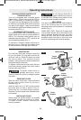
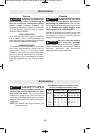
INSERTING BIT
For small bits, open jaws enough to insert the
bit up to the flutes. For large bits, insert the bit
as far as it will go. Center the bit as you close
the jaws by hand. This positions the bit
properly, giving maximum contact between the
chuck jaws and the bit shank.
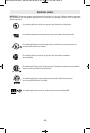
To tighten, hold the chuck collar firmly with one
hand and securely tighten the chuck sleeve
with the other hand (Fig. 2).
To prevent friction burns, or
pos sible hand injury, do not
loosen or tighten the chuck by using the power
of the drill.
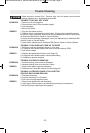
REMOVING CHUCK
Open the chuck all the way, remove left-hand
thread screw inside chuck by turning it
clockwise (Fig. 3).
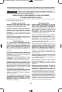
Insert the short arm of a 3/8" hex key wrench
and close jaws on flats of wrench (Fig. 4).
Strike long arm of wrench sharply counter-
clockwise, remove wrench and unthread chuck
from spindle.
INSTALLING CHUCK
Always keep the spindle threads, the threads
of the chuck and securing screw free of debris.
To install a chuck, reverse “removing the
chuck” procedure.
!
WARNING
Counter
Clockwise
Clockwise
CHUCK COLLAR
CHUCK
SLEEVE
FIG. 2
Counter
Clockwise
Counter
Clockwise
Clockwise
FIG. 3
FIG. 4
-8-
SM 2610032789 08-13_SM 2610032789 08-13.qxp 8/26/13 8:10 AM Page 8