7
THE POWER UNIT'S OPERATION - PE
Troubleshooting Guide for "PE" Series
Only qualified individuals trained to understand mechanical devices and their associated electrical and hydraulic circuits should
attempt troubleshooting and repair of this equipment.
Care should be taken to identify all potential hazards and comply with applicable safety procedures before beginning work.
Consult the factory for problems at time of installation, or for any problems not addressed below.
Before working on the power unit, always secure the lip plate outward and disconnect the power supply.
PROBLEM
Lever doesn't cycle when the
"RAISE" button is pressed.
POSSIBLE CAUSE
Motor doesn't run
Motor runs properly, but the deck doesn't
move or the lip doesn't extend. Motor and
pump not noisy.
Leveler raises but won't lower, or lowers
only slowly.
CORRECTIVE ACTION
• Use a multimeter to check: for proper supply (all
legs) and control voltage; for an "open anywhere
in the control circuit.
• Visually check for loose wiring or pushbutton
components.
• Verify the motor shaft rotates CCW.
• Ensure that the reservoir is full and that its fill
hole plug has been replaced by a breather plug.
• Check for items resting on the leveler.
• Install a pressure gauge to check hydraulic
system pressure. If it doesn't build to 1,500 psi,
consult the factory for a replacement pump.
• Remove, check and clean the pilot-operated
check valve.
• Remove, check and clean the pilot-operated
check valve and the flow control valve.
• Check for any binding of the mechanical parts;
hinge, etc.
E
N
G
L
I
S
H
The electric / hydraulic edge-o-dock leveler utilizes an electric motor directly coupled to a gear-type hydraulic pump to produce the
needed fluid pressure and flow to allow the cylinder(s) to perform the work of lifting the dockplate.
A hydraulic manifold houses the hydraulic control components, and is bolted directly onto the gear pump.
The power unit's hydraulic components are all rated for 3,000 psi working pressure.
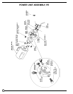
Important parts of power unit included:
• The electric motor. Motors are available for operaton on single- or three-phase AC supplies (all are dual-voltage capable.)
• The gear pump. Its shaft is coupled directly to the shaft of the electric motor.
• The check valve. Its purpose is to prevent the backflow of fluid through the pump.
• The pressure relief valve. Its job is to open a path for fluid to flow back to the reservoir in the event that the fluid pressure built up by
the pump exceeds 1,500 psi. Thus the system cannot see more than 1,500 psi.
• The pilot-operated check valve. This is a hydraulically-operated cartridge valve. It closes to allow oil flow to the cylinder(s) when the
system is under pressure, then opens to allow the levelers lip to fall when the system pressure drops after the motor turns off.
• The pressure-compensated flow control. This regulates the fluid flow from the cylinder(s) back to the reservoir when the
pilot-operated valve opens. It allows for the adjustment of the lip fall rate.
• The hydraulic lift cylinders(s).
• The hydraulic fluid. The system uses HO150 hydraulic fluid. Any anti-wear hydraulic fluid with an SUS viscosity of 150 - 200 at
100°F (SAE viscosity grade of 32) such as AW-32 or Dextron transmission fluid are acceptable.
When the leveler is to be extended, the operator presses the "RAISE" pushbutton. The motor turns, and in turning it spins the
hydraulic gear pump. Oil is drawn from the reservoir and into the pump. System pressure builds and causes the pilot-operated check
valve to close.
Once the lip extends out, the operator releases the pushbutton. The check valve prevents oil from from returning to the
reservoir through the pump. When the pressure in the hydraulic system drops sufficiently, the pilot-operated check valve opens
to allow the oil in the cylinder(s) to return back to the reservoir through the pressure-compenated flow control valve, which will
regulate the rate at which the lip lowers.
In the event that the lip won't raise, it will be necessary to remove the pilot-operated check valve for inspection and cleaning, as
follows:
• Secure the lip plate in the extended position to allow access to the power unit.
• Disconnect and lock out the leveler's power supply
• Remove the cartridge valve from the cavity marked POCV.
• Inspect for contaminants in the valve or the valve cavity.
• Wash the valve in mineral spirits or kerosene if possible. Blow off the valve with a compressed-air gun.
• Replace the valve and cycle the leveler several times.


