


"#!""
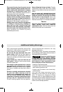
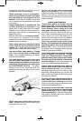
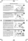
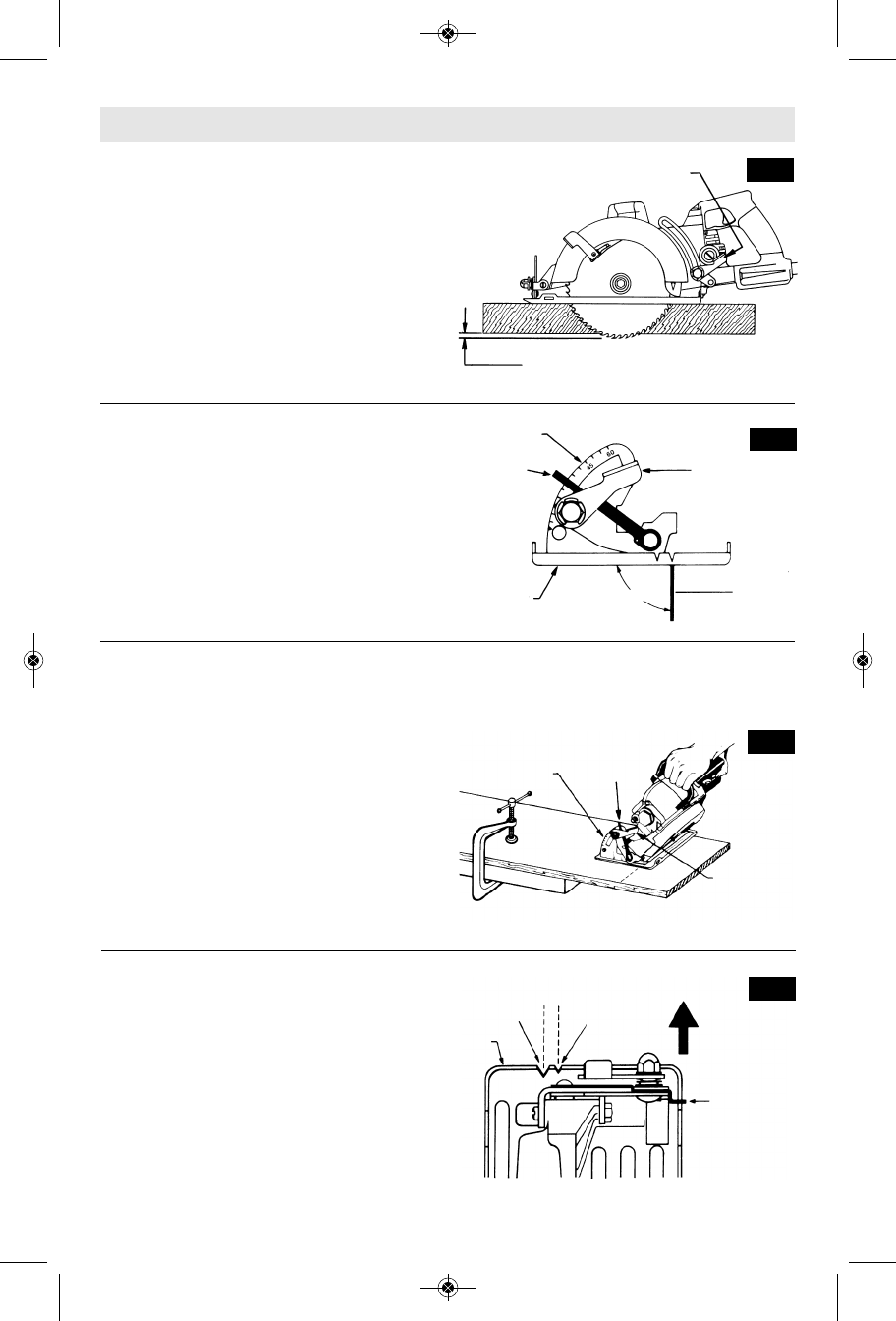
Disconnect plug from power source. Loosen
the depth adjustment lever located between
the guard and handle of saw. Hold the foot
down with one hand and raise or lower saw by
the handle. Tighten lever at the depth setting
desired. Check desired depth (Fig. 3).
Not more than one tooth length of the blade
should extend below the material to be cut, for
minimum splintering (Fig. 3).
-9-
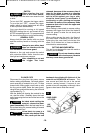
B#""
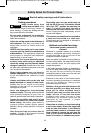
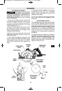
Disconnect plug from power source. Set foot to
maximum depth of cut setting. Loosen bevel
adjustment lever, set to 0° on quad rant,
retighten bevel adjustment lever first, then the
depth ad just ment lever and check for 90°
angle between the blade and bottom plane of
foot with a square (Fig. 4).
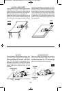
$#!""
Disconnect plug from power source. The foot
can be adjusted up to 45° by loosening the
bevel adjustment lever at the front of the saw.
Align to desired angle on calibrated quadrant.
Then tighten bevel adjustment first, then the
depth adjustment lever (Fig. 5). For 51° cuts,
loosen depth adjustment lever, align 51° mark
on depth bracket with mark on housing and
tighten lever (Fig. 1). Then loosen bevel
adjustment lever, depress 45° stop spring,
adjust foot to 51° and tighten lever (Fig. 5).
Because of the increased amount of blade
engagement in the work and decreased
stability of the foot, blade binding may occur.
Keep the saw steady and the foot firmly on the
workpiece.
7,9(;05.5:;9<*;065:
FIG. 3
DEPTH ADJUSTMENT LEVER
ONE TOOTH LENGTH SHOULD PENETRATE
WOOD FOR MINIMUM SPLINTERING
#
For a straight 90° cut, use the large notch in
the foot. For 45° & 51° bevel cuts, use the
small notch (Fig. 6). The cutting guide notch
will give an approximate line of cut. Make
sample cuts in scrap lumber to verify actual
line of cut. This will be helpful because of the
number of different blade types and
thicknesses available. To ensure minimum
splintering on the good side of the material to
be cut, face the good side down.
BLADE
90°
FOOT
BEVEL
ADJUSTMENT
LEVER
QUADRANT
FIG. 4
B
45° STOP
SPRING
QUADRANT
BEVEL
ADJUSTMENT
LEVER
FIG. 5
45° STOP
SPRING
FIG. 6
FOOT
45° / 51°
BEVEL
CUTS
90°
VERTICAL
CUTS
PUSH
45°STOP
SPRING IN
DIRECTION
OF ARROW
FOR 51° BEVEL
ADJUSTMENT
SM 1619X03173 11-08:SM 1619X03173 11-08 12/2/08 11:21 AM Page 9