Wall Console
The GC-433R Wall Console replaces most garage door “push buttons” or
“wall consoles”. There are 2 different kinds of “push buttons”:
- If you have a push button, you can replace the push button by the GC-433R.
- If you have a Chamberlain
®
, Lift-Master
®
, Sears
®
Multi-Functional Wall
Console, you can replace the push button by GC-433R.
Replace Connect in Parallel
All Brands - Push Button
Other Brands, other
Wall Consoles
Chamberlain
®
, Lift-Master
®
, Sears
®
-
Wall Console
Replace
1. Remove the existing screws holding the push
button of the wall console.
2. Disconnect the 2 wires that are connected to the
existing push button / wall console.
3. Connect these 2 wires to the 2 terminals on the
GC-433R wall console. Tighten the screws on
the terminals to secure the wiring.
4. Mount the GC-433R on to the wall with 2 screws
provided and straighten up its antenna for best
reception.
5. You may power up the garage door opener by
plugging in the AC cord.
6. Follow instructions in “Charging Up Wall Console
GC-433R”.
–1–
Congratulations on your purchase of the Skylink
®
Garage Door Closer
Model GT-100A. Skylink
®
Garage Door Closer is very easy to install,
and provides you with the peace of mind you have been looking for by
knowing your garage door will not be left open anymore. Skylink
®
Garage Door Closer consists of 2 units:
Wall Console does not require any battery to operate and it can replace
most of the existing garage door opener’s push buttons. Garage Door
Sensor is battery operated and can be mounted on to the garage door by
double sided tape or screws. These 2 units operate wirelessly which
simplifies the installation.
Programming is very simple, you can select the time you would like the
door to be closed after it has been opened. The selectable door closing
times are 2 minutes, 5 minutes, 10 minutes and 20 minutes.
1. INTRODUCTION
Model GT-100A
Garage Door Closer
Garage Door
Monitor
TM
Sensor
(Battery Included)
GS-101
2. INSTALLATION (CONT)
Before installing the Skylink
®
garage door closer, ensure your garage
door is equipped with an external entrapment protection device, such
as an infrared beam sensor which “sees” an object obstructing the door
without having actual contact with the object. A Garage door opener does
not have the auto reversing mechanism should be replaced by one that has
the auto reversing mechanism feature and the garage door closer
must not be installed on a garage door opener without this feature.
Without a properly working safety reversal system, a person could be
seriously injured or killed by a closing garage door.
WARNING
2. INSTALLATION
Unplug the power cord of your garage door opener
before installation to ensure power is not connected.
WARNING
The installation involves 2 units:
1) Garage Door Monitor
TM
Sensor
2) Wall Console
Garage Door Monitor
TM
Sensor
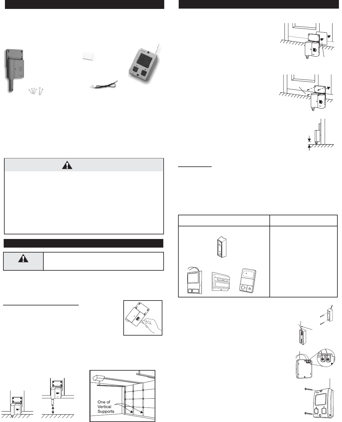
Step 1 – Select a spot on your garage door to mount
the sensor
Before you install the sensor on to the garage door,
make sure the garage door is closed. The sensor
assembly should be mounted on one of the vertical
supports of your garage door near the bottom.
When the door is closed, the detection rod should be retracted. When
the door is open, the detection rod will be extended.
Note:
When the garage door is opening/closing,
make sure the sensor does not interfere with
the safety reversing sensor or safety beam
sensor supplied with your existing garage
door opener.
Step 2 – Mount the sensor on to your garage door
You can mount the sensor on to your garage
door with double-sided foam tape if the sur-
face of your garage door is smooth and clean
enough to provide a good adhesive surface,
such surface can usually be found on a metal
garage door. Please ensure the surface is
smooth and clean. Important: The bottom
of the sensor should be 1/2 inch above
the ground. (Refer to Diagram A)
For wooden garage doors, it is recommended
to mount the sensor with screws on to the
garage door with 3 x 18 screws provided.
4 Screws
Double-sided
foam tape
1/2 Inch
Note: Ensure you straighten up the antenna
on the receiver to receive the best possible
reception.
Diagram A
Door closed
Door open
Remove the battery
isolator
4 pcs 3 x 18 screws
2 pcs 3.5 x 25 screws
Double-sided
foam tape
Extension wires
Wall Console
GC-433R
Remove
existing
wires


