


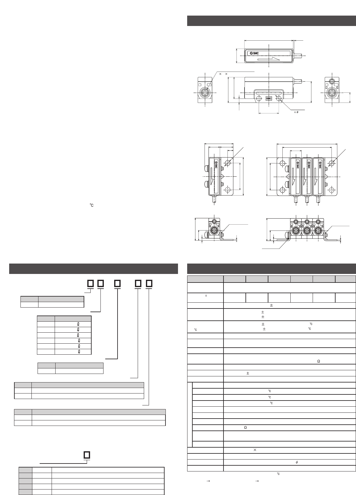
Specifications
•Prepare maintenance space.
•Do not drop or bump, or apply excess impact.
•Do not pull the lead wire forcefully, not lift the product by pulling the lead
wire. (Tensile force 49N or less).
•Mount a sensor by observing the proper tightening torque.
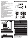
•Install or connect the flow sensor so that the flow direction specified on the
label matches with actual flow direction.
•Pipe the flow sensor after eliminating dust in piping by air blow to avoid
failure and malfunction.
•Use dry air which complies with the quality grade of ISO 8573-1 1.1.2 to
1.6.2 : 2001.
•If the entering of foreign material to the fluid is possible, install and pipe the
filter or the mist separator to the inle to avoid failure and malfunction.
•Avoid repeatedly bending or stretching the lead wire.
•Wire correctly.
•Do not wire while the power is supplied.
•Do not wire in conjunction with power lines or high voltage lines.
•Wire as short as possible to avoid the affect of noise and surge.
•Never use in the presence of explosive gases.
•Do not use in an area where magnetic field is generated to avoid
malfunction of sensor.
•Do not operate where the flow sensor is exposed to water.
•Do not use the sensor for poisonous substances, deleterious substances
and corrosive gas. This sensor is not a explosion proof. Do not use for
flammable gas.
•Do not apply heat cycle to the flow sensor.
•Do not used in an area where surges are generated.
•Sensors are not equipped with surge protection against lightening.
•Avoid using sensors in an environment where the likelihood of splashing or
spraying of water, chemicals, and oil to avoid failure and malfunction.
•Consider operating environment according to protection class.
•Do not use the flow sensor where exposed to vibration or impact. Vibration
may interfere correct measurement.
•Flow sensor has to be fixed when used.
•Operation under low temperature (5 or less) leads to cause damage or
operation failure due to frozen moist in the fluid or air.
•Do not short circuit the load.
• Maintenance and inspection should be performed periodically.
• Analog output may fluctuate by 2 to 3% for 5 minutes after supplying power
to the flow sensor.
• Do not poke inside a piping port with a stick.
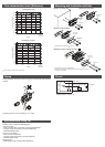
Dimensions and Names of Individual Parts (unit: mm)
2 M5 0.8 Thread depth 3.8
Piping
1IN 2
OUT
2 3.4
Mounting
15.2
14
3
0.8
7.1
(15)
10
34.4
18
FLOW SENSOR
2
OUT
FLOW SENSOR
L-type brack
et
(Tapped)
(25.7)
10 12
5
2 x 4.5
24
34
20
1
2
9.1
With L-type bracket
Note 1) Converted value of volume flow at ANR (20 , 101.3kPa, 65%R.H.).
Note 2) Analog output shows 3V when flow is zero. Changes to 5V side when flow direction is
IN OUT. 1V side when OUT IN.
Note 3) %F.S. in the table takes 4V (1-5V) as a full scale.
Note 4) 0kPa means release to the atmosphere.
Note 5) Applicable pressure range.
Note 6) Pressure range satisfies product specification.
Model
Measured fluid
Dry air, N2
(Air quality class is ISO 8573-1 1.1.2 to 1.6.2 : 2001)
Flow rate /min
Note1)
(measurement range)
2%F.S. or less
Note3)
Repeatability
2%F.S. or less (0 to 300kPa)
5%F.S. or less (-70 to 0kPa)
Pressure
characteristic
(0kPa reference
Note4)
)
2% F.S. or less (15 to 35 )
5% F.S. or less (0 to 50 )
-100kPa to 400kPa
500kPaProof pressure
At voltage output : 1 to 5V
Output impedance : approx. 1k
5ms or less (Response 90%)Response time
12 to 24VDC 10%, ripple(p-p) 10% or less (Protected against inverse connection)
IP40Enclosure
0 to 50 (No freezing or condensation)Operating fluid temp.
0 to 50 (No freezing or condensation)Operating temp. range
35 to 85%R.H. (No condensation)Storage humidity range
1000V AC, 1min Between battery and the bodyWithstand voltage
50M or more(500V DC Mega) Between battery and the body
10 to 150Hz 1.5mm amplitude
98m/s
2
acceleration in X, Y, Z directions for 2 hours(Power is not supplied)
Vibration resistance
980m/s
2
X, Y, Z directions 3 times for each(Power is not supplied)
Impact resistance
M5 0.8 (tightening torque : 1 to 1.5N•m or less)Port size
PPS, Si, Au, SUS316, C3604(Electroless nickel plating)Fluid contact material
3 core vinyl cabtire cable 2.6, 0.15mm
2
, 2mLead wire
10g (without lead wire)Weight
-10 to 60 (No freezing or condensation)Storage temp. range
16mA or lessPower consumption
Source voltage
-70kPa to 300kPaPressure rate
Note5)
Analog output
(Non-linear output)
Insulation resistance
Resistance
Temperature
characteristics
(25 reference)
Operating pressure
range
Note6)
35 to 85%R.H. (No condensation)Operating humidity range
PFMV505 PFMV530FPFMV505FPFMV530
0 to 0.5
-3 to 3
Note2)
-0.5 to 0.5
Note2)
0 to 3
PFMV510 PFMV510F
0 to 1 -1 to 1
Note2)
Model Indication Method
PFM - -
Output specification
Type
V5 Remote type sensor
ContentsModel
1Analog (1 to 5V)
ContentsModel
Measurement flow range
05
ContentsModel
0.0 to 0.5 /min
10
30
0.0 to 1.0 /min
0.0 to 3.0 /min
05F -0.5 to 0.5 /min
10F -1.0 to 1.0 /min
30F -3.0 to 3.0 /min
Operation manual
Nil
N
With Operation manual (in Japanese and English)
ContentsModel
Without Operation manual
Option(Included in the same package)
Nil
A
Without L-type bracket
Contents
Model
With 2 L-type brackets and 2 mount screws M3 x 15L included for 1station
ZS - 36 - A
L-type bracket
Stations
22 stns
1 stn1
44 stns
55 stns
3 stns
2 L-type brackets, 2 mount screws M3 x 25L included
2 L-type brackets, 2 mount screws M3 x 15L included
2 L-type brackets, 2 mount screws M3 x 45L included
2 L-type brackets, 2 mount screws M3 x 55L included
2 L-type brackets, 2 mount screws M3 x 35L included3
When optional part is needed by part alone, or to be mounted to the manifold,
please order by part number below.
10
34
24
10 x n + 24 (n=1 to 5)
10 x n + 14
2 x 4.5
20
9.1
2
1
OUT
FLOW SENSOR
FLOW SENSOR
FLOW SENSOR
2
OUT
2
OUT
2
L-type brack
et
(Through hole)
L-type brack
et
(Tapped)
Mount on one side
Mount on both sides