


2
3. BATTERY INSTALLATION
(Continued from Previous Page)
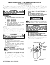
E. Connect over flow tube and route as shown in
Figure 2.
FIGURE 2
DISCHARGE DEFLECTOR
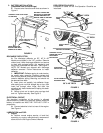
A. The discharge deflector on 33”, 42” & 48”
Models are shipped in the “UP” position. Remove
rubber band, lower discharge deflector and secure
to deck with carriage bolt(s), flat washer(s) and
wing nut(s) furnished with the deck. See Figure 3.
NOTE: 38” Models are shipped with discharge
deflector removed. Follow instructions to install
deflector.
1. IMPORTANT: Deflector spring is under tension,
be careful when removing. Remove carriage bolt
and nut that secures pivot rod to the deck. Pivot rod
contains deflector spring. Mounting rod should not
be removed from deck.
2. Insert pivot rod partially into deflector hinge,
slide spring onto rod with straight leg on top, then
insert rod through other hinge and then into
mounting rod. Insert hooked end of spring into deck.
See Figure 3.
3. Secure pivot rod to deck using carriage bolt
and nut. Tighten securely. See Figure 3.
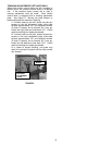
ELECTRICAL CIRCUIT
The electrical connection at the engine is shipped
disconnected to protect the electrical system when the
battery is installed and MUST BE THE LAST STEP in
preparation.
A. Connect electrical circuit at rear of the engine.
See Figure 4.
LUBRICATION and FUEL
1. Engine
A. Perform normal engine service, oil and fuel,
according to engine manufacturer’s recommend-
ations found in the Engine Owner’s Manual.
PRE-OPERATION CHECK
Complete all items on the Pre-Operation Checklist as
instructed.
FIGURE 3
FIGURE 4
CONNECT OVER FLOW TUBE
TO BATTERY
BATTERY CABLES ARE
INSTALLED AT THIS TIME
SHOWN REMOVED FOR
BETTER VIEW OF BATTERY
INSERT TUBE INTO HOLE
IN SEAT PEDESTAL
ONCE INSTALLED
ROUTE TUBE AWAY
FROM TOP OF DECK
42” DECK
INSTALL NUTS
HERE
33” DECK
INSTALL NUTS
HERE
DEFLECTOR SPRING
STRAIGHT LEG OF
SPRING ON TOP OF
DISCHARGE
DEFLECTOR
38” & 48” DECK
DISCHARGE
DEFLECTOR
DO NOT REMOVE
MOUNTING ROD
CARRIAGE
BOLT
SPRING
SLOT IN
PIVOT
ROD
LOCKNUT